Vacuum heat-preserving tube

A technology of vacuum insulation and vacuum chamber, applied in the direction of heat preservation, pipeline protection through heat insulation, pipeline protection, etc., can solve the problems of vacuum insulation pipe damage, linear expansion difference, high operating cost, etc., achieve low cost, reduce consumption, and facilitate transportation Effect

Inactive Publication Date: 2006-09-27
张丽娟
View PDF1 Cites 11 Cited by
  • Summary
  • Abstract
  • Description
  • Claims
  • Application Information

AI Technical Summary

Problems solved by technology

[0002] Based on the Chinese patent with the authorized announcement number CN2395126Y, a utility model of a steel-sheathed steel high-temperature-resistant composite vacuum insulation pipe, which includes a working steel pipe, an inorganic insulation layer, an organic insulation layer, a protective layer, etc., has a complex structure, is difficult to manufacture, and has other advantages. The defect of high operating costs; At present, there are other types of vacuum insulation pipes, which have not been solved. Due to the difference in linear expansion of the inner and outer pipes due to temperature differences, the problem of damage to the vacuum insulation pipes is caused.

Method used


Image

  • Vacuum heat-preserving tube
  • Vacuum heat-preserving tube
  • Vacuum heat-preserving tube

Examples


Embodiment 1

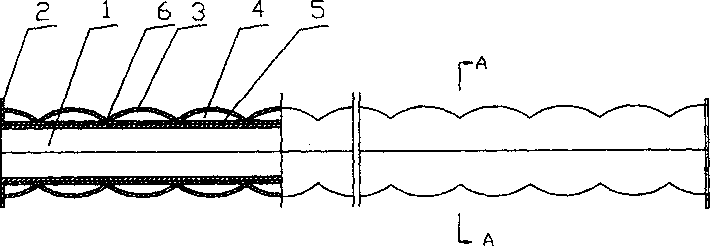
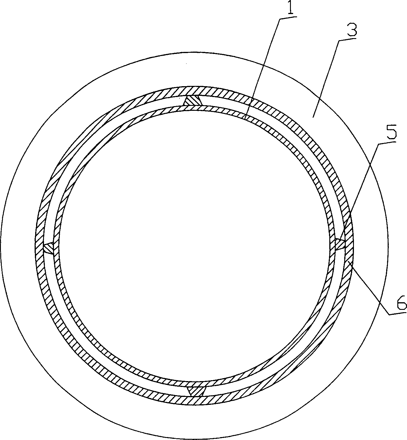
[0022] Embodiment 1: as figure 1 with image 3 As shown, the vacuum insulation pipe includes a pipe body 1 with flanges 2 at both ends of the pipe body 1; it is characterized in that: the outside of the pipe body 1 is covered with a sleeve 3 with a continuous corrugated structure, which is connected with the pipe body 1 and the flange. 2 together form a vacuum chamber 4; the outer wall of the tube body 1 is provided with a number of continuous or discontinuous support ribs or support points 5 along the axial direction of the tube body 1, and each inner edge 6 of the corrugated structure of the casing 3 is supported on the support ribs or support points 5 , the purpose of which is to make the vacuum chambers between the corrugations communicate.

Embodiment 2

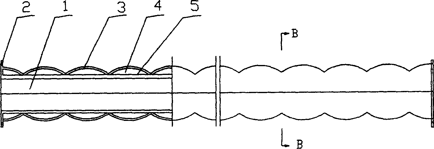
[0023] Embodiment 2: as figure 2 with Figure 4 As shown, the vacuum insulation pipe includes a pipe body 1 with flanges 2 at both ends of the pipe body 1; it is characterized in that: the outside of the pipe body 1 is covered with a sleeve 3 with a continuous corrugated structure, which is connected with the pipe body 1 and the flange. 2 together form a vacuum chamber 4; each inner edge 6 of the corrugated structure of the sleeve 3 has a number of small gaps 7 (the purpose is to make the vacuum chambers between the corrugations communicate), and each inner edge 6 of the corrugated structure of the sleeve 3 supports on body 1.

Embodiment 3

[0024] Embodiment 3: as figure 2 with Figure 5 As shown, the vacuum insulation pipe includes a pipe body 1 with flanges 2 at both ends of the pipe body 1; it is characterized in that: the outside of the pipe body 1 is covered with a sleeve 3 with a continuous corrugated structure, and the sleeve is arranged along its radial direction. It is continuously corrugated, and at the same time, the circumference along its cross section is also


PUM


Abstract

The invention relates to a vacuum thermal-insulated tube, which comprises a tube whose two ends are connected with flanges. It is characterized in that: the tube is sheathed with a sheath with continuous ripple structure to form a vacuum chamber. The invention has simple structure and improved stress relation to avoid crack caused by the temperature difference between inner and outer tubes. And the ripple structure can release the tube change, to reduce the cost of connecting tube. The invention has lower cost and wider application for transmitting high-temperature water or steam.

Description

technical field [0001] The vacuum insulation pipe of the present invention is especially a vacuum insulation pipe for transporting water or steam. Background technique [0002] Based on the Chinese patent with the authorized announcement number CN2395126Y, a utility model of a steel-sheathed steel high-temperature-resistant composite vacuum insulation pipe, which includes a working steel pipe, an inorganic insulation layer, an organic insulation layer, a protective layer, etc., has a complex structure, is difficult to manufacture, and has other advantages. The defect of high operating costs; at present, there are other types of vacuum insulation pipes, which have not been solved. Due to the difference in linear expansion of the inner and outer pipes due to temperature difference, the problem of damage to the vacuum insulation pipe is caused. Contents of the invention [0003] The technical problem to be solved by the present invention is to overcome the defects of the prio...

Claims


Application Information

Patent Timeline
Patent Type & Authority Applications(China)
IPC IPC(8): F16L59/147F16L59/06
Inventor 张丽娟
Owner 张丽娟
Why Eureka
Try Eureka