
Differential force type magnetic suspension water level gauge

A technology of magnetic levitation and water level gauge, which is applied in the direction of buoy liquid level indicator, etc., can solve the problems of easy leakage, lag, and reduced measurement accuracy of ground water level gauge, and achieve the effect of not easy to leak and high precision.

Inactive Publication Date: 2006-09-27
刘瑞
View PDF0 Cites 5 Cited by
  • Summary
  • Abstract
  • Description
  • Claims
  • Application Information

AI Technical Summary

Problems solved by technology

Although these water level gauges have their own characteristics, they also have their own defects. For example, the local water level gauge is easy to leak, and the mica sheet is fouled, which seriously affects its display effect; the electric contact water level gauge measures the water level through the electrode, and the electrode The number of settings is limited, and there is a certain interval between the electrodes, which reduces the measurement accuracy and cannot eliminate the problem of blind spots; the differential pressure water level gauge measures the water level through the reference water level of the water, and cannot be real-time because there is no reference water level when starting the furnace. Put into operation; the magnetic levitation water level gauge measures the water level by measuring the position of the float, and the float must overcome its own gravity and the friction between the float and the inner wall of the container when it floats upward under the action of buoyancy, which will inevitably bring about hysteresis problems and reduce the measurement accuracy

Method used


Image

  • Differential force type magnetic suspension water level gauge

Examples


Embodiment Construction

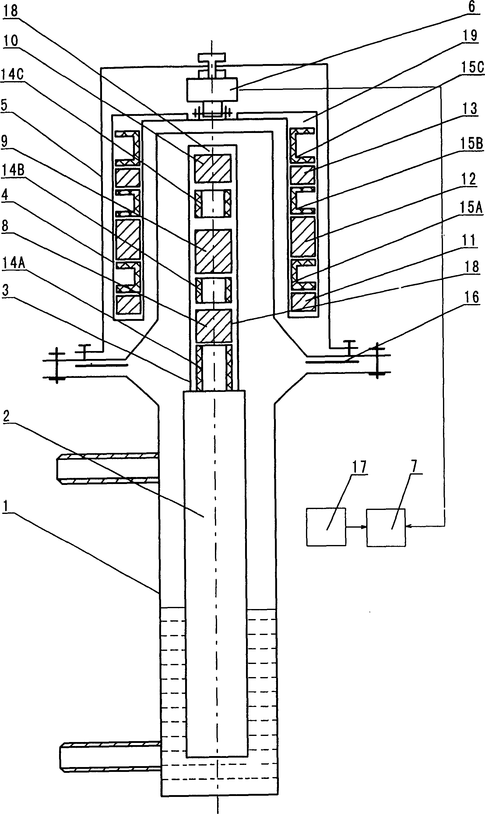
[0008] The present invention as figure 1 As shown, a cylindrical structure is adopted, and the upper straight pipe section of the container 1 is connected with the lower part of the container 1 by a flange connection, and the joint is sealed with an annular gasket 16 .

[0009] The measuring hammer 2 is columnar and placed vertically in the container 1 . The inner magnetic steel assembly 18 includes inner magnetic steel columns 8, 9, 10, the three are cylindrical, stacked in the inner magnetic steel sheath 3, and separated by annular spacers 14A, 14B, 14C, the inner magnetic steel sheath The lower end of the sleeve 3 is welded to the upper end of the measuring hammer 2 . The lower end of the support 5 is also connected with the straight pipe section of the container 1 in the form of a flange. The upper end of the tension transmitter 6 is fixed on the bracket 5 with bolts, and the measuring end is connected with the outer magnetic steel sheath 4 with connecting bolts. The ou...


PUM


Abstract

This invention relates to a differential force type magnetic suspension water level gauge, which comprises a containment drum connected to the boiler by two pipes, a measurement hammer stable suspended in the drum by the interaction of n=magnetic fields formed by following alnicos, an inner alnico fixed on hammer upper end by an inner alnico sheath, a bracket with lower end fixed on the drum, a tension transmitter fixed on bracket upper end, an outer alnico connected to the transmitter measurement end by an outer alnico sheath, and a water-level display secondary meter connected to the signal output end of the transmitter. This invention can measure continually with high precision.

Description

technical field [0001] The invention belongs to the technical field of water level measurement and relates to a differential force magnetic levitation water level gauge. Background technique [0002] At present, there are many measurement methods in the field of water level measurement, such as: local direct reading water level gauge, differential pressure water level gauge, electric contact water level gauge, magnetic levitation water level gauge, etc. Although these water level gauges have their own characteristics, they also have their own defects. For example, the local water level gauge is easy to leak, and the mica sheet is fouled, which seriously affects its display effect; the electric contact water level gauge measures the water level through the electrode, and the electrode The number of settings is limited, and there is a certain interval between the electrodes, which reduces the measurement accuracy and cannot eliminate the problem of blind spots; the differentia...

Claims


Application Information

Patent Timeline
IPC IPC(8): G01F23/68G01F23/64
Inventor 刘瑞刘立峰
Owner 刘瑞
Learn More