
Detection device for adhesion amount of color toner

A measuring device and a technology for adhesion amount, which are applied in scattering characteristics measurement, electrography, polarization influence characteristics, etc., can solve the problems of increased component cost and assembly cost, increased number of processes, deviation of measurement accuracy, etc., so as to improve the installation Accuracy, realization of compact structure, and effect of reducing deviation

Active Publication Date: 2006-09-27
STANLEY ELECTRIC CO LTD
View PDF2 Cites 7 Cited by
  • Summary
  • Abstract
  • Description
  • Claims
  • Application Information

AI Technical Summary

Problems solved by technology

[0024] For this reason, the number of components increases, and in addition to the dimensional variation of each component, the measurement accuracy of the color toner adhesion amount measuring device 1 varies due to the variation of the mounting accuracy on the substrate 7, and the component cost and assembly cost increase. , the light source 1a also becomes larger
[0025] In addition, the third photodiode 9 for monitoring needs to be sealed with a sealing resin 9a after being mounted on the substrate 7 in order to eliminate the influence of external disturbance, which increases the number of steps and increases the manufacturing cost.
[0026] On the other hand, in the toner adhesion amount measuring device 1 of the above-mentioned Patent Document 1, there is no special configuration for monitoring the light intensity of the light source and controlling the light intensity.
[0027] In addition, in the color toner adhesion amount measuring device 1 of the above-mentioned Patent Document 2, although it is configured to monitor the light quantity of the light source, since a part of the light from the light source is divided and monitored by the light division means, it should be irradiated to the detection body ( Part of the light on the photoreceptor) is used for monitoring, resulting in a decrease in the amount of light irradiating the object

Method used


Image

  • Detection device for adhesion amount of color toner
  • Detection device for adhesion amount of color toner
  • Detection device for adhesion amount of color toner

Examples


Embodiment 1

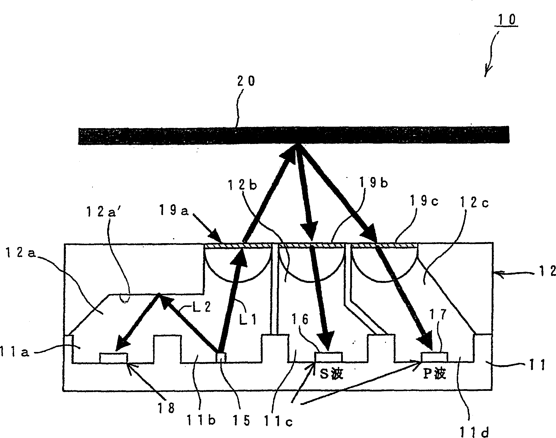
[0057] figure 1 The structure of one embodiment of the color toner adhesion measuring device of the present invention is shown.

[0058] exist figure 1 Among them, the color toner adhesion measurement device 10 includes a frame member 11 and a cover 12 .

[0059] The frame member 11 is formed in a flat rectangular parallelepiped shape made of resin, and has four depressed portions 11a, 11b, 11c, and 11d arranged in a row.

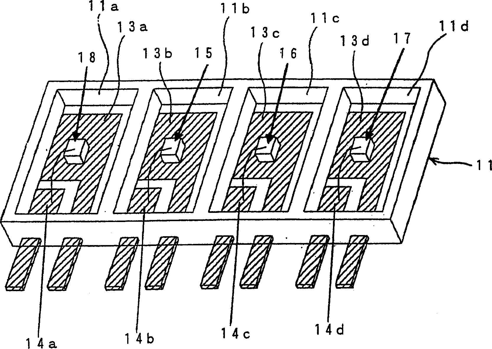
[0060] In each recessed portion 11a, 11b, 11c, 11d, as figure 2 As shown, there are respectively a pair of conductive parts 13a, 14a, 13b, 14b, 13c, 14c and 13d, 14d facing each other and exposed on their bottom surfaces.

[0061] These conductive parts 13a, 14a, 13b, 14b, 13c, 14c and 13d, 14d are integrally formed with the frame member 11 by, for example, insert molding, and the other ends protrude from one side of the frame member 11 to form lead terminals.

[0062] Here, if figure 1 and figure 2 As shown, in the second concave portion 11b, a ...


PUM


Abstract

The objective of the invention is to provide a simply, inexpensively and compactly configured device for measuring the adhesion amount of color toner having a monitor function by simple configurations. This color toner adhesive amount measuring device 10 comprises a frame member 11 made of resin equipped with four recessed sections opened to an upper direction, a pair of conductor parts 13 and 14 exposed so as to be made adjacent to each other on the bottom face of each recessed section of the frame member, one chip-shaped light emitting element 15 and three chip-shaped light receiving elements 16, 17 and 18 mounted at the chip mounting part of one conductor part 13 in each recessed section, and electrically connected to the other conductor part and one cover 12 covering the frame member. The cover is provided with a window part having polarizing films 19a, 19b and 19c corresponding to the light emitting element and the first and second light receiving elements and a reflecting surface 12a' for reflecting the rays of light from the light emitting element to the third light receiving element.

Description

technical field [0001] The present invention relates to a color toner adhesion measuring device for measuring the adhesion amount of color toner in a transfer type color printer, a color facsimile device, and the like. Background technique [0002] In the past, this kind of color toner adhesion measurement device, for example, is based on Figure 4 composition shown. [0003] That is, in Figure 4 Among them, the color toner adhesion measuring device 1 is made up of the following parts: LED (light emitting diode) 2 as the light-emitting part; Be configured in the first beam splitter (beam splitter) 3 in the light-emitting light path of LED 2; The first photodiode 4 and the second photodiode 5 ; and the second beam splitter 6 arranged in the light receiving path of these photodiodes 4 and 5 . [0004] And, the color toner adhesion amount measuring device 1 is disposed in a light source (lamp house) 1a as a whole, and as shown in FIG. Figure 5 is mounted on a substrate 7 as...

Claims


Application Information

Patent Timeline
IPC IPC(8): G01N21/21G01N21/47G03G15/01G03G15/00G03G15/08
Inventor 村田知之
Owner STANLEY ELECTRIC CO LTD
Learn More