
Data transfer control device and electronic instrument

一种数据传输控制、控制器的技术,应用在数字传输系统、数据处理的输入/输出过程、传输系统等方向,能够解决显示位置错位、包接收恶劣影响等问题

Inactive Publication Date: 2006-09-27
SEIKO EPSON CORP
View PDF1 Cites 39 Cited by
  • Summary
  • Abstract
  • Description
  • Claims
  • Application Information

AI Technical Summary

Problems solved by technology

[0005] However, when using this method to realize serial transmission, once there is some noise on the serial transmission line, it will have a bad influence on the reception of the packet
It has been proved that, especially when the host device outputs the synchronous signal (vertical synchronous signal, horizontal synchronous signal) for the RGB interface and the target side regenerates the synchronous signal, due to the noise attached to the serial transmission line, the misalignment of the display position occurs question

Method used


Image

  • Data transfer control device and electronic instrument
  • Data transfer control device and electronic instrument
  • Data transfer control device and electronic instrument

Examples


Embodiment Construction

[0043] Next, preferred embodiments of the present invention will be described in detail. Moreover, the embodiments described below do not improperly limit the protection scope of the claims, and not all the structures described in this embodiment are necessary for solving the technical problems of the present invention.

[0044] 1. System configuration

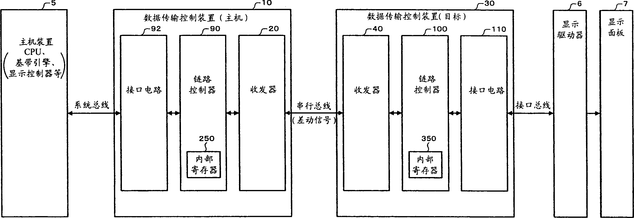
[0045] figure 1 It is a schematic diagram of a configuration example of the data transmission control device (data transmission control circuit) and its system of the present embodiment. In this example, by using figure 1 The data transmission control devices 10 and 30 on the host side and the target side of the system implement the so-called bridging function between the system bus and the interface bus.

[0046] In addition, the data transmission control device 10, 30 is not limited to figure 1 composition, its structure can be omitted figure 1 A part of the circuit module can also change the connection state between the ...


PUM


Abstract

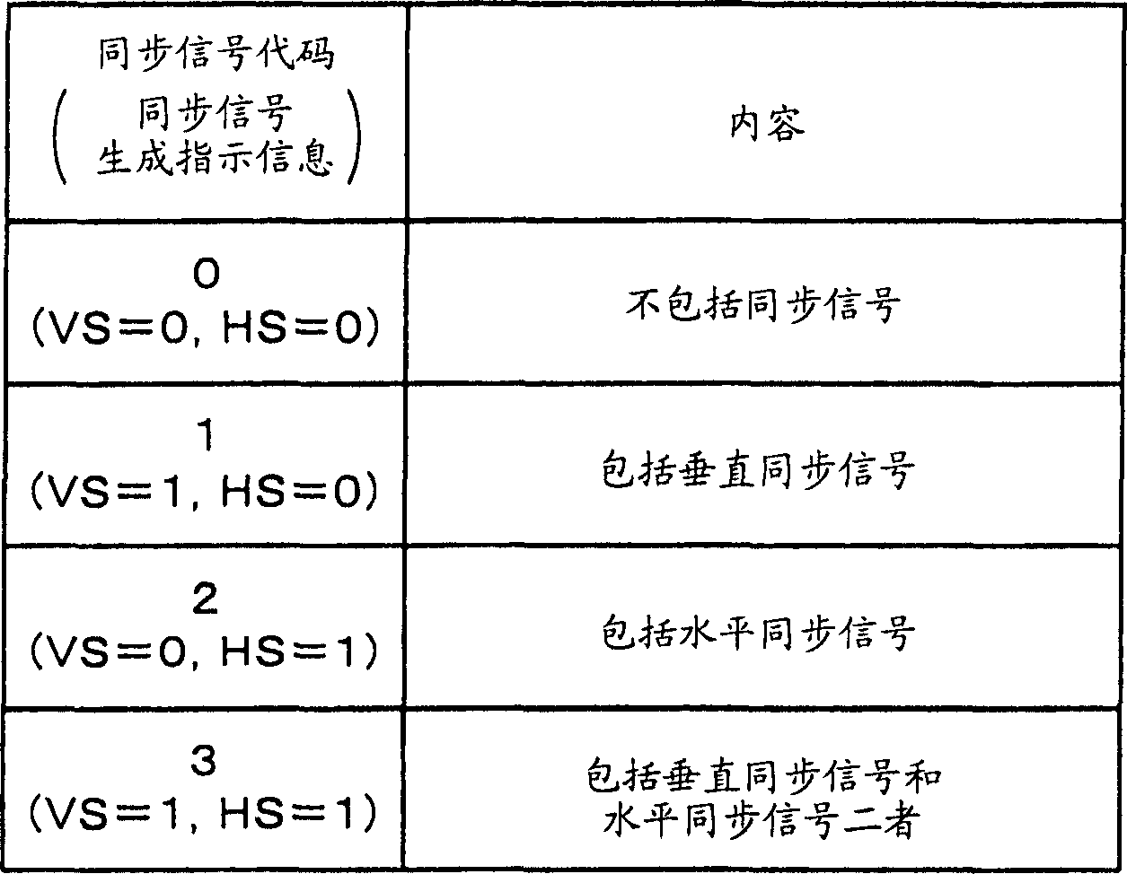
A data transfer control device includes: a link controller which analyzes a packet received through a serial bus; an interface circuit which generates interface signals and outputs the interface signals to an interface bus; and a reset signal output circuit which outputs a reset signal to the interface circuit. The link controller analyzes a packet to determine whether or not the received packet includes synchronization signal generation direction information (synchronization signal code). The reset signal output circuit outputs the reset signal to the interface circuit when the link controller has determined that the received packet includes the synchronization signal generation direction information.

Description

technical field [0001] The invention relates to a data transmission control device and electronic equipment. Background technique [0002] In recent years, high-speed serial transmission interfaces such as LVDS (Low Voltage Differential Signaling) have drawn attention as interfaces aimed at reducing EMI noise and the like. In these high-speed serial transmissions, the transmitting circuit uses differential signals to transmit serialized data, and the receiving circuit differentially amplifies the differential signals, thereby realizing data transmission. [0003] A general portable phone is composed of the following parts: a first device part provided with keys for telephone number input and text input; a second device part provided with a main LCD, a sub-LCD and a camera; connecting the first device part and the second device Part of the hinge and other connecting parts. Therefore, if the serial transmission method of differential signals is used to transmit data between ...

Claims


Application Information

Patent Timeline
Patent Type & Authority Applications(China)
IPC IPC(8): G06F13/42G06F3/147G09G3/36
CPCH04L7/041G09G5/006G06F13/00G06F13/14G06F13/38
Inventor 本田裕康
Owner SEIKO EPSON CORP
Learn More