Swivel joint for construction machine

A technology of construction machinery and rotary joints, which is applied in construction, mechanical equipment, pipes/pipe joints/fittings, etc. It can solve problems such as difficulty in completely preventing water from entering, corroded rotary joints are stuck, and poor workability, etc., to achieve replacement operations Easy, compact piping, improved dust resistance

Active Publication Date: 2006-09-27
NIHON KENKI CO LTD
View PDF3 Cites 8 Cited by
  • Summary
  • Abstract
  • Description
  • Claims
  • Application Information

AI Technical Summary

Problems solved by technology

However, the dust seal is mainly used to prevent the entry of dust, and it is difficult to completely prevent the entry of water.
In addition, there are cases where muddy water enters from the sliding gap between the lower end of the body and the main shaft, causing corrosion and seizure of the rotary joint due to rust.
[0007] In the body fixed type rotary joint, there is also the problem of dust resistance, because the sliding gap between the upper end of the body and the main shaft is in a position where dust such as water, soil and sand easily enters and accumulates
[0008] In addition, in the spindle fixed type rotary joint, since the body and the metal parts for piping connection are located on the lower side of the main frame of the rotary body, there is also the problem of poor workability when replacing the rotary joint. When rotating the joint, the operator must put his hand through the gap between the opening of the main frame of the revolving body and the body to connect and remove the piping on the side of the body.

Method used


Image

  • Swivel joint for construction machine
  • Swivel joint for construction machine
  • Swivel joint for construction machine

Examples


Embodiment Construction

[0027] Embodiments of the present invention will be described below with reference to the drawings.

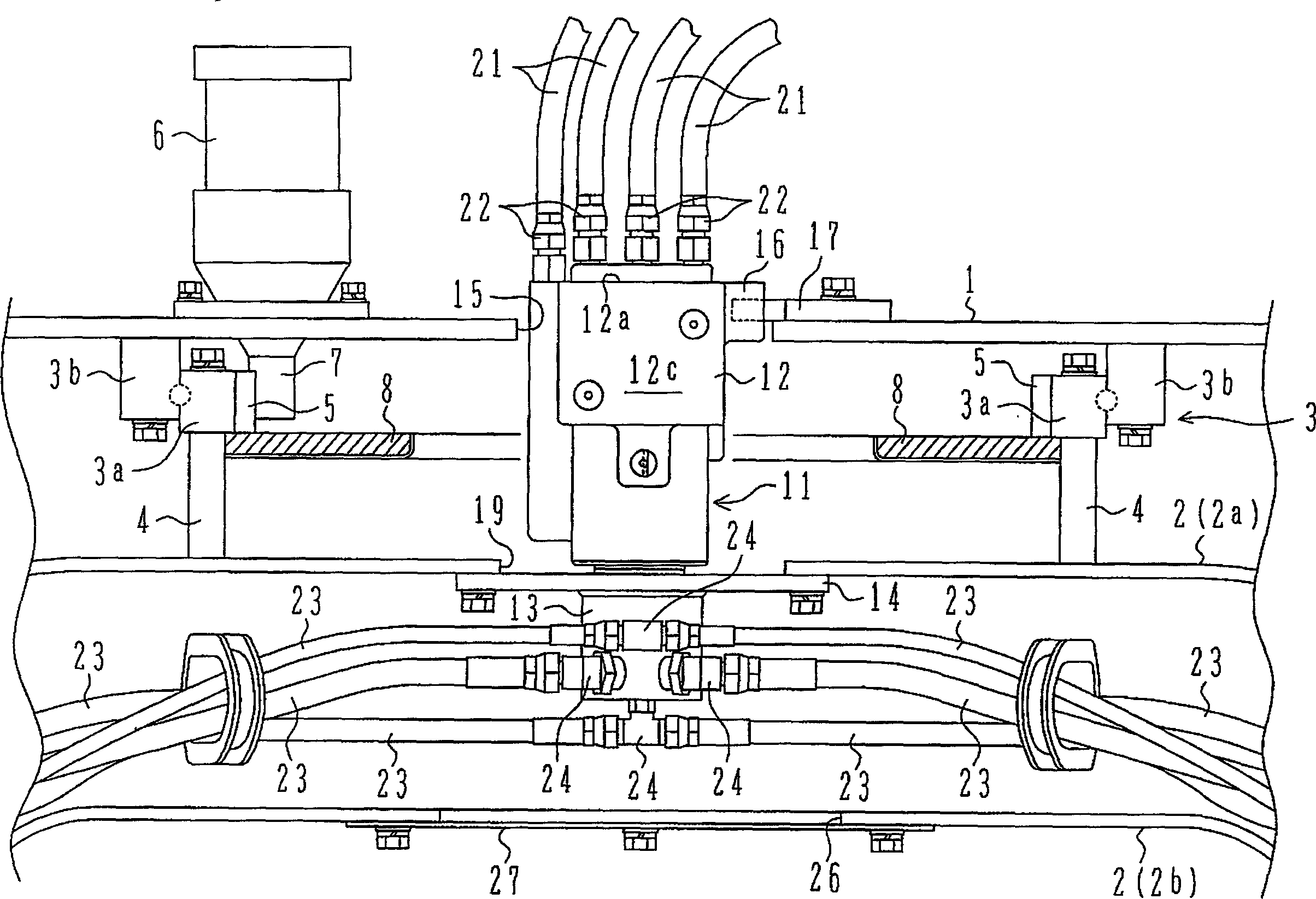
[0028] figure 1 It is a figure which shows the state which mounted the swivel joint of this invention between the revolving body and the traveling body of a hydraulic excavator.

[0029] exist figure 1 Among them, the symbol 1 is the main frame forming the bottom of the revolving body, and the symbols 2a and 2b are the upper track frame and the lower track frame constituting the track frame 2 of the walking body. The slewing wheel 3 composed of an inner ring 3a and an outer ring that can rotate relative to each other is located between the main frame 1 and the upper crawler frame 2a. On the wheel support portion 4, the outer ring 3a is fixed to the lower surface of the main frame 1 by bolts. The inner side of the inner ring 3 a is cut into a gear 5 with internal teeth, which meshes with a pinion 7 provided on the output shaft of the swing motor 6 . The rotary motor 6 is fi...


PUM


Abstract

A swivel joint for a construction machine, in which dust prevention characteristics and workability in replacement are improved. A spindle (13) of a swivel joint (11) is attached to an upper track frame (2a), and a stopper projection (16) of a body (12) is engaged with a stopper plate (17) in an opening section (15) of the rotating body main frame (1) so that the body (12) rotates together with a rotating body main frame (1). Rotating body side piping (21) is collectively connected by metallic members (22) to the upper end surface of the body (12), and traveling body side piping (23) is connected by metallic members (24) to a lower section of the spindle (13). A side surface of the body (12) has thick wall sections (31, 32), axial paths (33, 34) communicating with circumferential grooves (41) are provided in the thick wall sections, the axial paths are opened at the upper surface of the body, and the rotating body side piping (21) is collectively connected to the upper surface.

Description

technical field [0001] The present invention relates to a rotary joint of a construction machine such as a hydraulic excavator and a hydraulic crane having a revolving body provided on a running body in a rotatable manner. Background technique [0002] The rotary joint of construction machinery mentioned refers to the connecting piping between the hydraulic mechanism such as the valve device for controlling the travel motor installed on the revolving body and the hydraulic mechanism such as the travel motor installed on the travel body A rotary joint connected in a freely rotatable manner has a body and a main shaft rotatably inserted into the body. A plurality of circumferential grooves are formed between the inner peripheral surface of the body and the outer peripheral surface of the main shaft, and a plurality of axial channels are formed in the main shaft, by means of which the The communication state between the multiple pipes of the machine and the multiple pipes conn...

Claims


Application Information

Patent Timeline
Patent Type & Authority Applications(China)
IPC IPC(8): E02F9/12
CPCE02F9/2275F16L27/093B66C23/84E02F9/006E02F9/12E02F9/08
Inventor 川本纯也山田一德钓贺靖贵伊藤健二
Owner NIHON KENKI CO LTD
Why Eureka
Try Eureka