
Fuel battery apparatus possessing recirculated work fuel

A technology of fuel cells and fuel cell units, applied in the direction of fuel cells, fuel cell additives, transportation fuel cell technology, etc., to eliminate the risk of explosion, improve the overall efficiency, and achieve the effect of coupling

Inactive Publication Date: 2006-10-04
ROBERT BOSCH GMBH
View PDF0 Cites 2 Cited by
  • Summary
  • Abstract
  • Description
  • Claims
  • Application Information

AI Technical Summary

Problems solved by technology

[0008] A further disadvantage is that the electrical energy consumption of the compressor is on the order of about 2 kW with a vehicle drive power of 80 kW

Method used


Image

  • Fuel battery apparatus possessing recirculated work fuel
  • Fuel battery apparatus possessing recirculated work fuel

Examples


Embodiment Construction

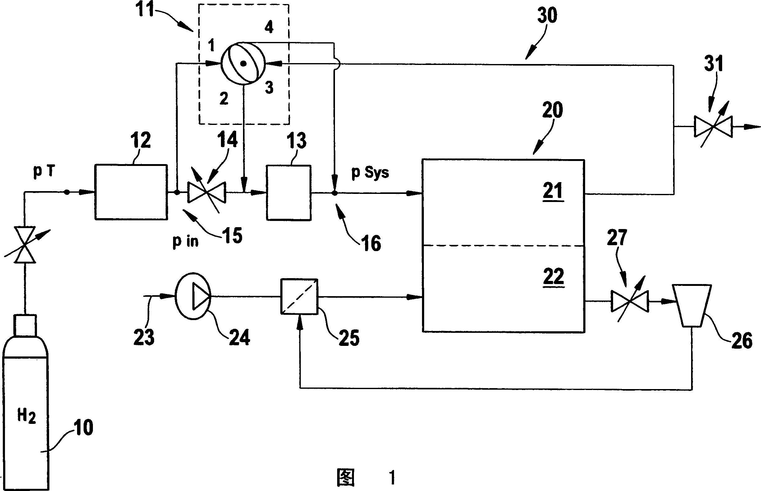
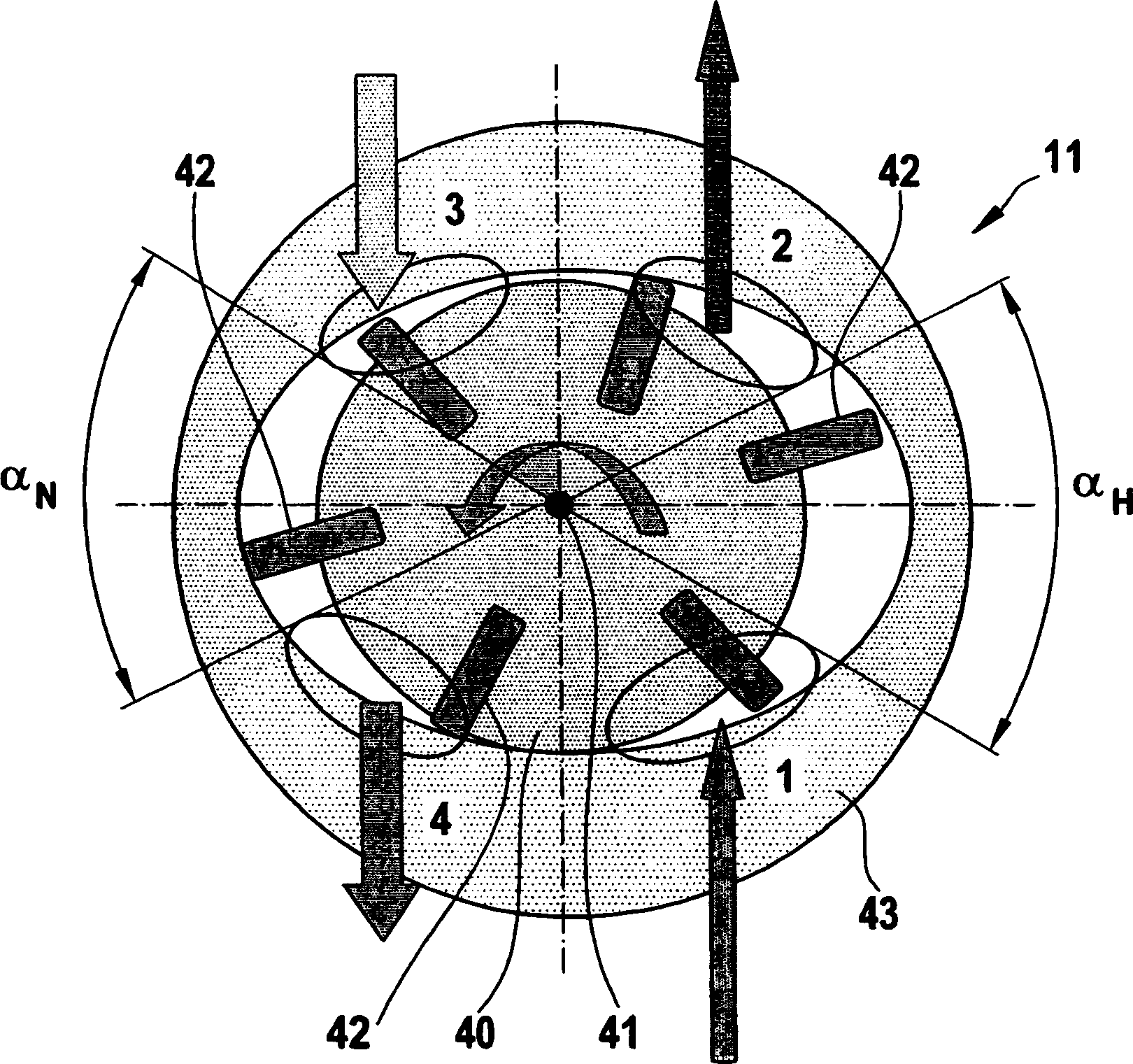
[0030] FIG. 1 schematically shows the basic structure of a fuel cell system with a compressor 11 driven by the high pressure of primary fuel or hydrogen 10 . The primary hydrogen 10 flows into the compressor 11 through a pressure reducing valve 12 using a bore. A compressor 11 is arranged in the flow direction of the hydrogen 10 downstream of a pressure regulator 12 which decompresses the hydrogen 10 from eg 12 bar to eg 9 bar-10 bar (absolute). The initial pressure on bore 1 is reduced to a pressure on bore 2 of eg about 9-10 bar (absolute) on the drive part of a compressor 11 which may also be called a so-called HRB (Hydrogen Recirculation Blower).

[0031] Partially decompressed hydrogen 10 flows from compressor 11 to hydrogen metering unit 13 (HMD: hydrogen metering device).

[0032] Between the pressure regulator 12 and the hydrogen metering unit 13 is provided a bypass 14 comprising an adjustable flow valve 15 (eg valve). Hydrogen 10 can thus be delivered to fuel cell ...


PUM


Abstract

A fuel cell system has a fuel cell unit including an anode, and a recirculation unit for recirculating hydrogenous operating material flowing out of the fuel cell unit back into the fuel cell unit, wherein the recirculation unit has at least one drive unit for driving a flow of an operating material, and the drive unit is configured as a pneumatic drive unit or hydraulic drive unit for utilizing an energy of a fluid.

Description

technical field [0001] The invention relates to a fuel cell system with a fuel cell unit comprising an anode according to the preamble of claim 1 . Background technique [0002] Interest in hydrogen as a future energy carrier has grown significantly in recent years. In particular, fuel cells operating with hydrogen can generate electricity and heat in an environmentally friendly manner. The efficiency of fuel cells is not limited by the Carnot cycle. The use of correspondingly high efficiencies makes it possible, for example, to preserve fossil resources and to reduce the dependence on fossil resources with regard to the use of fuel cells in vehicles or combined heat and power plants. [0003] Especially for automotive applications, so-called PEM fuel cells (Polymer Electrolyte Membrane Fuel Cells) are currently also used, in which proton-conducting polymer membranes are used which are required for hydrogen which is currently as pure a fuel as possible. In the case of aut...

Claims


Application Information

Patent Timeline
Patent Type & Authority Applications(China)
IPC IPC(8): H01M8/04H01M8/00
CPCY02E60/50Y02T90/32H01M2250/20H01M8/04097Y02T90/40
Inventor W·斯特罗尔G·本特利昂T·-H·阮-沙弗K·雷曼M·鲍尔勒H·舒内德G·温克勒T·海德
Owner ROBERT BOSCH GMBH
Learn More