Compressed air type mechanical part cleaning machine and use method thereof

A technology for compressed air and mechanical parts, applied in the field of compressed air mechanical parts cleaning machines, can solve the problems of difficult real-time monitoring of parts, low efficiency of manual cleaning, and sparks, so as to eliminate the risk of combustion and explosion, The effect of eliminating the risk of sparks

Active Publication Date: 2015-11-18
ZHEJIANG SIEKON PRECISION MACHINERY CO LTD
View PDF6 Cites 2 Cited by
  • Summary
  • Abstract
  • Description
  • Claims
  • Application Information

AI Technical Summary

Problems solved by technology

[0002] For parts with cleanliness quality requirements such as auto parts, bearings, engines, steam turbines, aviation, semiconductors, data storage, medical equipment, etc., the usual practice is to use nylon brushes with NY-120 solvent oil (or absolute ethanol, three Chloromethane, aviation washing gasoline, 95% ethanol, trichlorethylene, etc.) to clean the surface of parts, the efficiency of manual cleaning is very low, and it is difficult to monitor the parts produced in real time. In order to achieve real-time monitoring of the cleanliness of production line products, it is necessary Improve the cleaning speed of parts, and use ordinary small cleaning machines to clean parts
Ordinary small cleaning machines have an electrical control system and an explosion-proof motor (or pump) power transmission device. During operation, the electrical control system will generate sparks, and the moving parts of the power transmission system will rotate. The friction between each other will generate heat, and it is flammable when used. , Explosive cleaning fluid, there is a great potential safety hazard

Method used


Image

  • Compressed air type mechanical part cleaning machine and use method thereof
  • Compressed air type mechanical part cleaning machine and use method thereof

Examples


Embodiment Construction

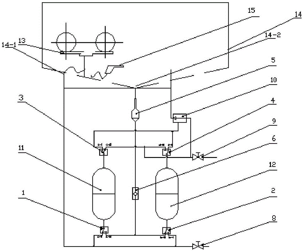
[0025] The compressed air type mechanical parts cleaning machine comprises a cleaning chamber 14 and a cleaning liquid circulation system. The cleaning chamber 14 is provided with a workbench 13 (the workbench 13 can rotate 360°), a cleaning chamber inflow port 14-1 connected to the spray gun 15 and The cleaning chamber outlet 14-2; the cleaning liquid circulation system includes a cleaning liquid filter 5 (preferably, the cleaning liquid filter 5 is U-shaped, and the U-shaped bottom is provided with a groove for containing impurities, and the outlet of the filter is provided with There are filters), one-way valve 6, pressure vessel 11 and liquid storage tank 12; the two ends of pressure vessel 11 are respectively provided with three-way valve a1 and three-way valve c3, the interface a-1 of three-way valve a1 and the flow of cleaning chamber The inlet 14-1 is connected, the interface a-2 of the three-way valve a1 is connected with the one-way valve 6; the interface c-1 of the t...


PUM


Abstract

The invention relates to the field of production and manufacturing, and particularly relates to a compressed air type mechanical part cleaning machine, and the invention further provides a use method of the compressed air type mechanical part cleaning machine. The compressed air type mechanical part cleaning machine comprises a cleaning chamber and a cleaning liquid circulating system, wherein the cleaning chamber is provided with a workbench, a spray gun, a cleaning chamber inflow opening and a cleaning chamber outflow opening, and the cleaning chamber inflow opening and the cleaning chamber outflow opening are connected with the spray gun; the cleaning liquid circulating system comprises a cleaning liquid filter, a check valve, a pressure vessel and a liquid storage tank; through the conversion of four three-way valves, the pressure vessel and the liquid storage tank alternately realize the functions of a cleaning tank and the liquid storage tank by utilizing a vacuum generator and compressed air. The cleaning machine is not provided with an electric control system, so that the risk of sparks is avoided; a driving component is not arranged in the whole cleaning machine, so that high temperature of the cleaning machine cannot happen, thereby avoiding the risks of burning and explosion of a common small cleaning machine, and the effects of safety and no hidden danger are really achieved.

Description

technical field [0001] The invention relates to the field of production and manufacturing, in particular to a compressed-air mechanical parts cleaning machine, and also provides a method for using the compressed-air mechanical parts cleaning machine. Background technique [0002] For parts with cleanliness quality requirements such as auto parts, bearings, engines, steam turbines, aviation, semiconductors, data storage, medical equipment, etc., the usual practice is to use nylon brushes with NY-120 solvent oil (or absolute ethanol, three Chloromethane, aviation washing gasoline, 95% ethanol, trichlorethylene, etc.) to clean the surface of parts, the efficiency of manual cleaning is very low, and it is difficult to monitor the parts produced in real time. In order to achieve real-time monitoring of the cleanliness of production line products, it is necessary Improve the cleaning speed of the parts, and use an ordinary small cleaning machine to clean the parts. Ordinary small...

Claims


Application Information

Patent Timeline
Patent Type & Authority Applications(China)
IPC IPC(8): B08B3/02B08B3/08B08B13/00
CPCB08B3/02B08B3/08B08B13/00B08B2203/02
Inventor 廖君单澜
Owner ZHEJIANG SIEKON PRECISION MACHINERY CO LTD
Why Eureka
Try Eureka