Bed body supporting device for X ray machine
A supporting device and X-ray machine technology, which is applied in the direction of patient positioning for diagnosis, etc., can solve the problems of internal welding slag and iron filings, difficulty in eliminating welding stress, and inconvenient processing, so as to reduce welding processing costs and avoid deformation , The effect of convenient processing
- Summary
- Abstract
- Description
- Claims
- Application Information
AI Technical Summary
Problems solved by technology
Method used
Image

Examples
Embodiment 1
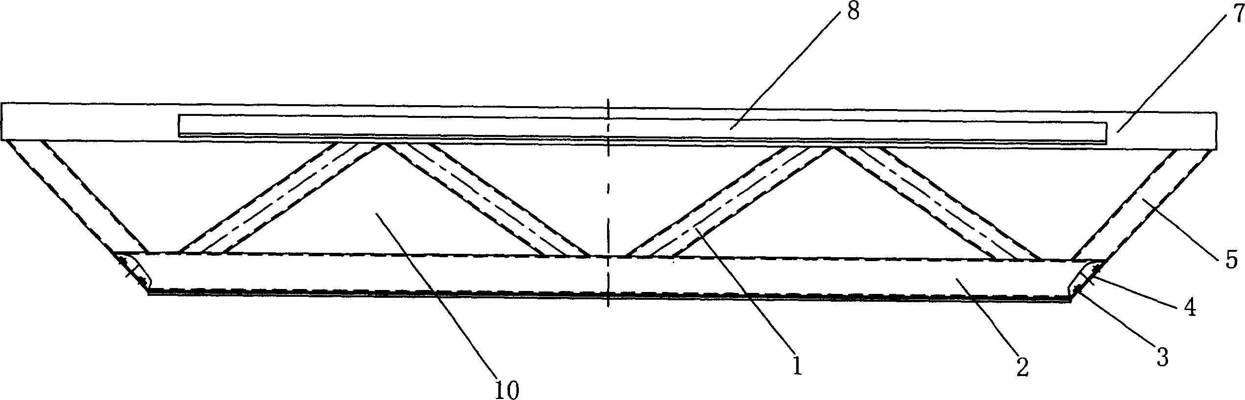
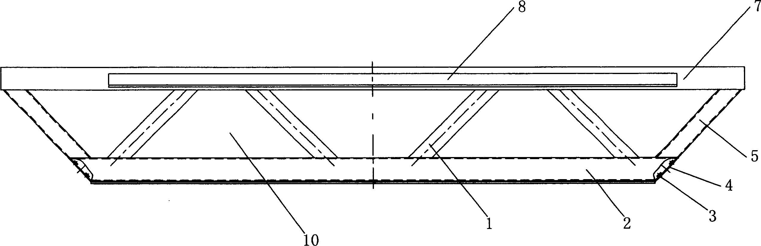
[0013] Embodiment 1: a kind of bed supporting device for X-ray machine, such as figure 1 , figure 2 Shown, its structure comprises upper beam 7, lower beam 2, side beam 5 and supporting column 1, and side beam 5 is installed between the two ends of upper beam 7, lower beam 2, forms boat-shaped skeleton structure; Four support columns 1 are arranged between the beam 7 and the lower beam 2, and the support columns 1 on both sides of the center line of the boat-shaped skeleton structure are symmetrically arranged to ensure that the force of the support device is balanced and uniform; the support column 1, the side beam 5 and the Three trapezoidal and two triangular chambers 10 are formed between the upper beam 7 and the lower beam 2, such as figure 1 shown, or form five trapezoidal chambers 10, such as figure 2 As shown; the supporting column 1 and the lower beam 2 are hollow structures, and the present embodiment selects square steel, and on the lower beam 2, holes are arr...
Embodiment 2
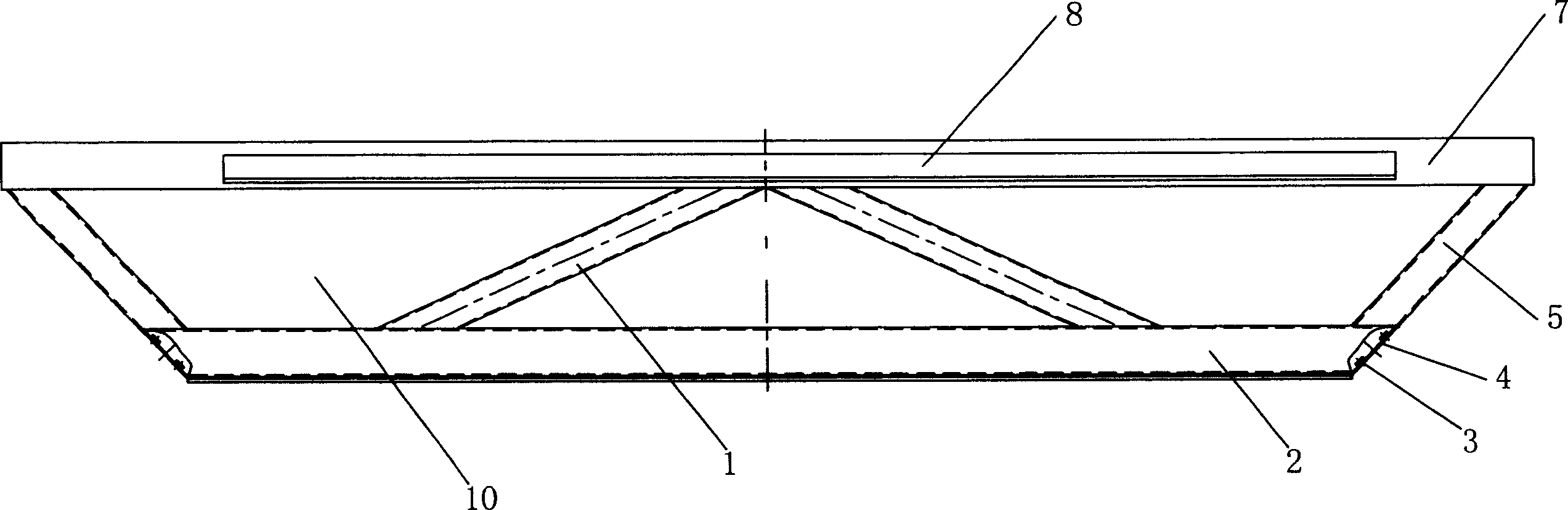
[0014] Embodiment 2: as image 3 , Figure 4 As shown, its overall structure is the same as that of Embodiment 1, the difference is: two supporting columns 1 are arranged between the upper beam 7 and the lower beam 2, the supporting column 1, the side 5 beams and the upper beam 7, and the lower beam 2 Two trapezoidal and one triangular alternate chambers are formed between them, such as image 3 shown, or form three trapezoidal chambers 10, such as Figure 4 shown.
Embodiment 3
[0015] Embodiment 3: as Figure 5 , Image 6 As shown, its overall structure is the same as that of Embodiment 1, the difference is that six supporting columns 1 are arranged between the upper beam 7 and the lower beam 2, the supporting columns 1, the side 5 beams and the upper beam 7, and the lower beam 2 4 trapezoidal and 3 triangular alternate chambers 10 are formed between them, such as Figure 5 shown, or form seven trapezoidal chambers 10, such as Image 6 shown.
[0016] In order to alleviate the gravity of the device itself and meet the requirements of strength, the upper beam 7 and the side beam 5 can be made of square steel, U-shaped steel or L-shaped steel; A flange 4 is installed at the hole 3 for decoration, and a decorative plate 6 is packaged on both sides of the boat-shaped skeleton structure, and the decorative plate 6 is a thin steel plate or iron plate for wrapping and decoration; The liner plate 8 installed on the top is connected with other devices; af...
PUM
 Abstract
Description
Claims
Application Information
 - R&D
- Intellectual Property
- Life Sciences
- Materials
- Tech Scout
- Unparalleled Data Quality
- Higher Quality Content
- 60% Fewer Hallucinations
Browse by: Latest US Patents, China's latest patents, Technical Efficacy Thesaurus, Application Domain, Technology Topic, Popular Technical Reports.
© 2025 PatSnap. All rights reserved.Legal|Privacy policy|Modern Slavery Act Transparency Statement|Sitemap|About US| Contact US: help@patsnap.com