Hanging type air disinfection device for respiratory infectious disease

A technology for air disinfection and infectious wards, which is applied in the field of medical equipment to achieve high efficiency, thorough disinfection and reasonable design

Inactive Publication Date: 2006-10-11
SHAANXI NORMAL UNIV
View PDF0 Cites 6 Cited by
  • Summary
  • Abstract
  • Description
  • Claims
  • Application Information

AI Technical Summary

Problems solved by technology

According to the search, the existing air disinfection and purification equipment and patents cannot solve this problem well

Method used


Image

  • Hanging type air disinfection device for respiratory infectious disease
  • Hanging type air disinfection device for respiratory infectious disease
  • Hanging type air disinfection device for respiratory infectious disease

Examples


Embodiment 1

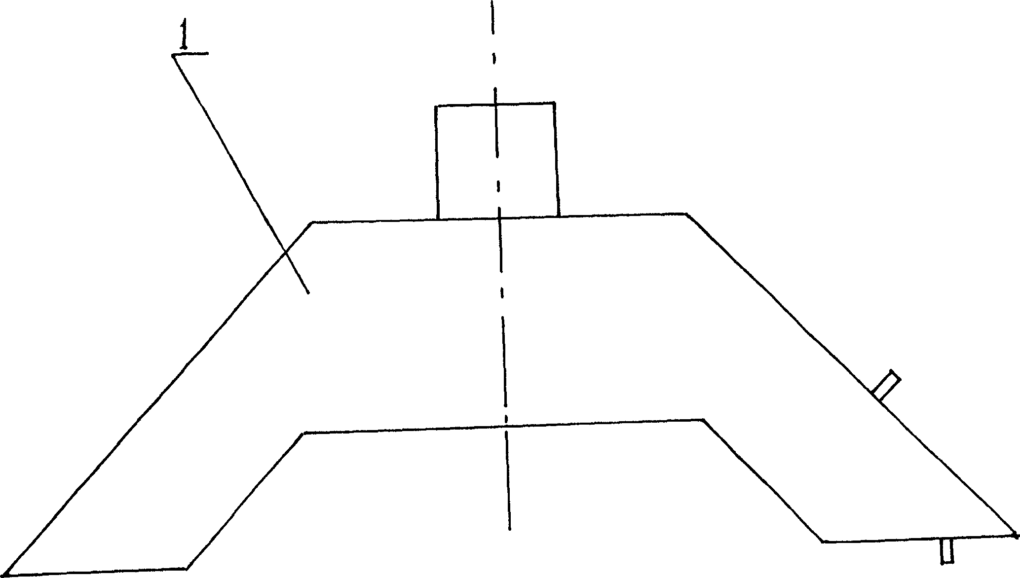
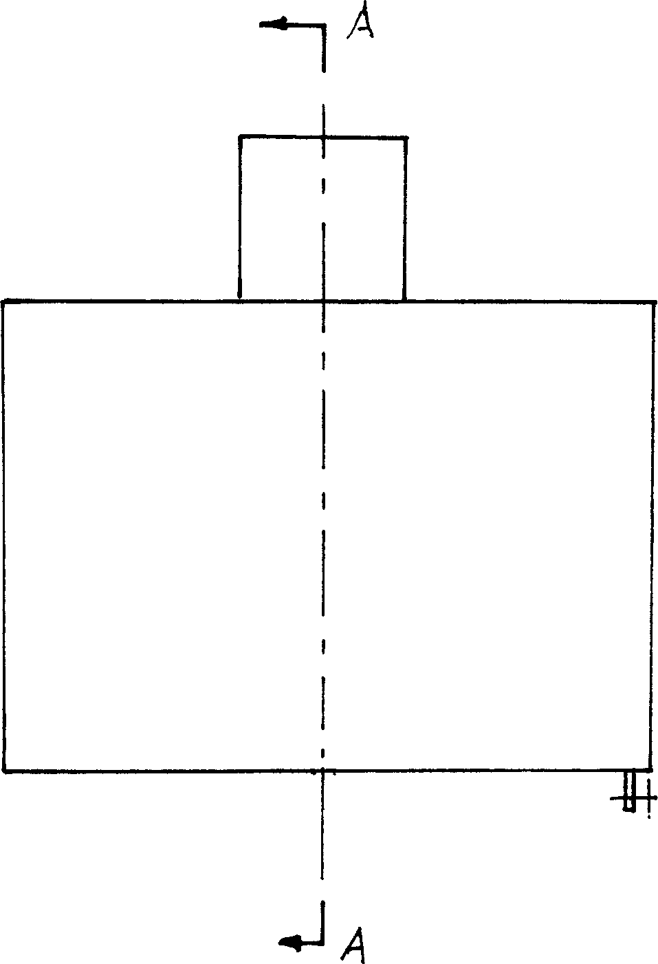
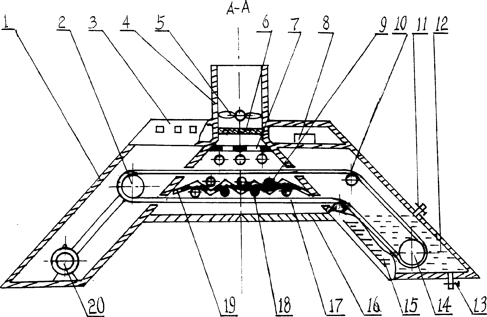
[0021] exist Figure 1~4 Among them, the wall-mounted air disinfection device for the respiratory infectious ward of the present embodiment is composed of a housing 1, a drive shaft 2, a control panel 3, an air outlet pipe 4, an axial flow fan 5, an activated carbon filter felt 6, a photocatalytic net 7, and an ultraviolet lamp. Power supply 8, ultraviolet lamp 9, guide shaft 10, liquid injection valve 11, disinfectant 12, liquid discharge valve 13, driven shaft 14, liquid level scale 15, air inlet louvers 16, disinfection belt 17, quartz electric heating tube 18, inlet The tuyere photocatalytic net 19 and the tuyere speed regulating motor 20 are connected to form.

[0022] The casing 1 of this embodiment is herringbone-shaped, and an air inlet louver 16 is installed on the lower air inlet of the casing 1 , and the angle of the air inlet louver 16 is symmetrical to the midline of the air inlet and parallel to the two inner surfaces of the casing 1 . The polluted air in the wa...

Embodiment 2

[0025]In this embodiment, the photocatalytic net 19 of the air inlet and the photocatalytic net 7 of the air outlet are 50 mesh surfaces with nano-TiO 2 The stainless steel mesh, the angle between a curved surface of the wave-shaped air inlet photocatalytic net 19 and an adjacent curved surface is 30 °, and the disinfectant 12 in the disinfectant chamber is a hydrogen peroxide aqueous solution with a concentration of 2%. The thickness of disinfection belt 17 is 3mm, and the thickness of activated carbon filter felt 6 is 3mm. Other components and the coupling relationship of the components are the same as in Embodiment 1.

Embodiment 3

[0027] In this embodiment, the photocatalytic net 19 of the air inlet and the photocatalytic net 7 of the air outlet are 60 meshes with nano-TiO on the surface. 2 stainless steel mesh, the angle between a curved surface of the wave-shaped air inlet photocatalytic net 19 and an adjacent curved surface is 150 °, and the disinfectant 12 in the disinfectant chamber is a 4% aqueous hydrogen peroxide solution. The thickness of disinfection belt 17 is 5mm, and the thickness of activated carbon filter felt 6 is 6mm. Other components and the coupling relationship of the components are the same as in Embodiment 1.


PUM

PropertyMeasurementUnit
thicknessaaaaaaaaaa
thicknessaaaaaaaaaa
thicknessaaaaaaaaaa

Abstract

The invention relates to a wall hanging air decontaminating apparatus for avoiding respiratory infections. The air inlet on shell is equipped with air inlet blinds; the upper part of shell is equipped with air outlet pipe; the left inner side of shell is equipped with adjustable speed motor, drive shaft connected with adjustable speed motor through belt; the antiseptic solution room in the right inner side of shell is equipped with antiseptic solution, guide shaft, and driven shaft; the drive shaft, driven shaft and guide shaft are equipped with sterilizing belt; the right side of shell is equipped with solution injecting valve and water-level gage; lower part of right side is equipped with solution discharge valve; inner right side is equipped with power for ultraviolet lamp; air inlet blinds is equipped with photocatalysis net and quartz electrothermal tube; said photocatalysis net is equipped with ultraviolet lamp; an air outlet photocatalysis net is equipped in shell; air outlet is equipped with active char filtering blanket and axial fan; a control board is installed on shell. The invention is characterized by rational design, simple structure, fast sterilizing speed, high efficiency and thorough sterilization. It is can be used for sterilization of ward and operating room and discharging of toxic gas in laboratory.

Description

technical field [0001] The invention belongs to the technical field of medical equipment, and in particular relates to a wall-mounted air disinfection device for a respiratory infection ward. Background technique [0002] Air disinfection and purification in respiratory infection wards has always been the top priority of hospital disinfection. Its purpose is to prevent virus infection and spread among patients, between patients and medical care and accompanying staff, and between respiratory wards and the outside world. At present, the air disinfection and purification of wards mainly adopts ozone disinfection, ultraviolet disinfection, ultrasonic atomization of various disinfectants 12 disinfection and various independently operated air disinfection and purification machines. The previous disinfection instruments can achieve a certain effect, but the person must leave the ward or the patient must be strictly protected during disinfection, and the disinfection is often carr...

Claims


Application Information

Patent Timeline
Patent Type & Authority Applications(China)
IPC IPC(8): A61L9/00A61L101/22A61L101/04
Inventor 张宗权
Owner SHAANXI NORMAL UNIV
Why Eureka
Try Eureka