A guide channel type electric combined-car traffic system
A public transport system and guide trough technology, which is applied in the field of guide trough electric train public transport system, can solve the problems of traffic congestion, environmental pollution, energy shortage, etc., and achieve the effect of convenient riding, flexible maneuvering and less space occupation
- Summary
- Abstract
- Description
- Claims
- Application Information
AI Technical Summary
Problems solved by technology
Method used
Image
Examples
Embodiment 1
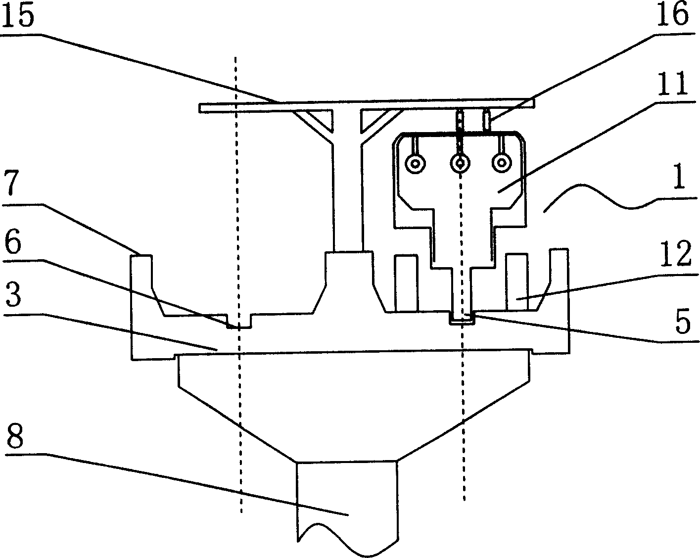
[0026] figure 1 It is a schematic diagram of the elevated structure of the present invention. In the figure, the power transmission frame 15 is installed on the train 1, the power transmission frame 15 is connected with the train 1 through the pole 16, and protective retaining walls 7 are installed on both sides of the road surface 3 to protect the train 1 Normal operation plays a role in safety. The road surface 3 is below the pier 8, thereby realizing the present invention to be 5 meters from the ground and 6.4 meters wide. The guide groove 6 is installed on the road surface 3, wherein the width of the guide groove 6 is 20 centimeters. The device 5 is mounted between corresponding tires 12 of the train.
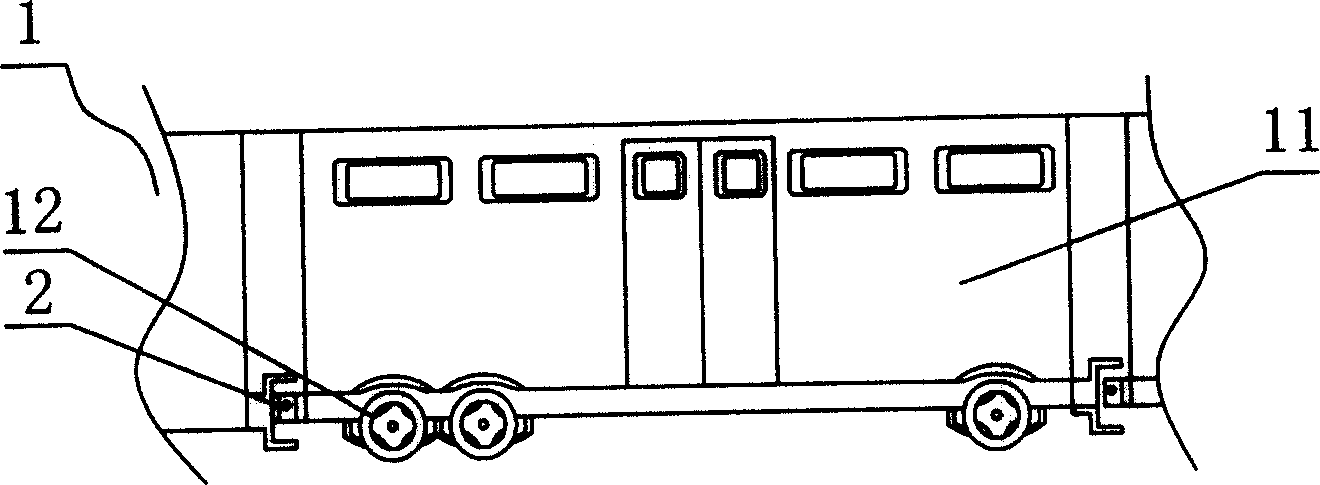
[0027] image 3 It is a train schematic diagram of the present invention. In the figure, each joint compartment 11 of the train 1 is connected and fixed by the compartment connector 2, and there are doors between adjacent compartments 11 to facilitate passengers to get on ...
Embodiment 2
[0035] The difference between this embodiment and embodiment one is: what the train 1 of the present invention passes through is a bifurcation crossing, see Figure 9 In the figure, the guide groove 6 includes a straight guide groove 66, a left row guide groove 67, a right row guide groove 68, three linkage reversing shafts 64, and two guide baffles 69, and the straight guide groove 66 extends into the left and right respectively Left row guide groove 67, right row guide groove 68, are provided with more than one guide baffle plate 69 on the intersection position of straight row guide groove 66, left row guide groove 67, right row guide groove 68, straight row guide groove 66, left row guide The interlocking reversing shaft 64 that cooperates with each other is also respectively installed on the groove 67 and the right row guide groove 68 .
[0036] When the present invention was used, the guide device 5 and the guide groove 6 worked together, and the train 1 moved in one dire...
Embodiment 3
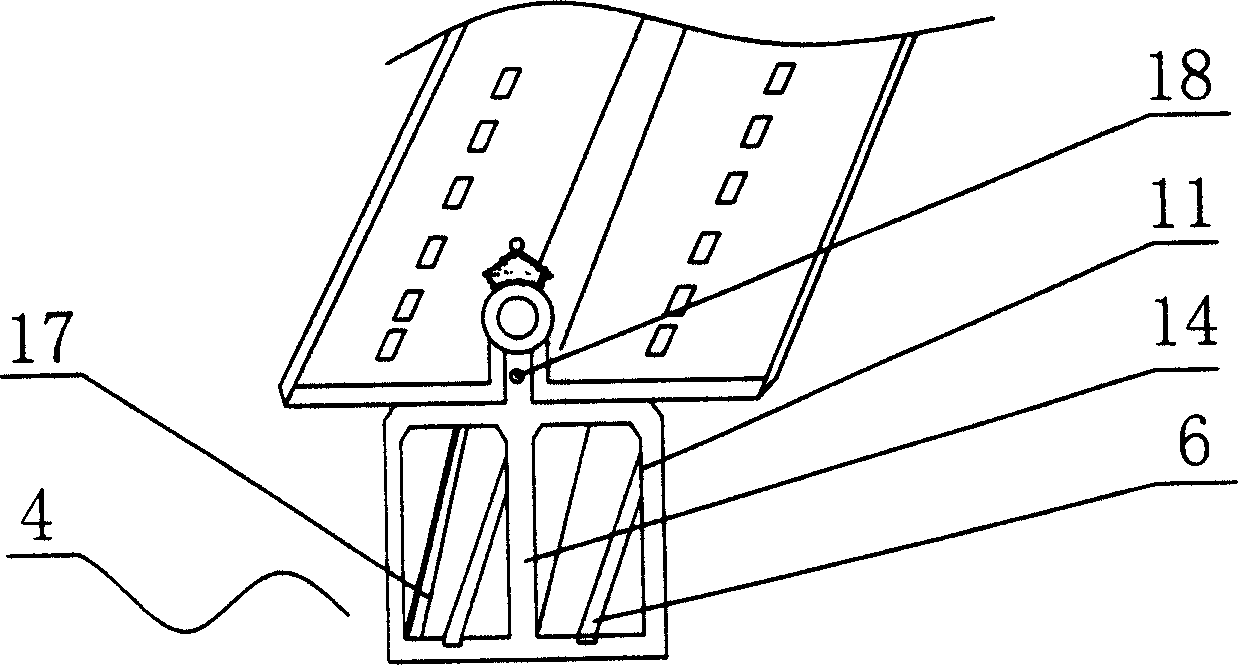
[0038] The difference between this embodiment and Embodiments 1 and 2 is that this embodiment adopts a surface structure, see figure 2 , in the figure, the conductive ground rail 17 and the guide groove 6 are all installed in the ground surface 4 and work together with the train 1, the corresponding left and right carriages 11 are provided with intercommunication holes 14, and the carriages 11 are also provided with ventilation holes 18, wherein the intercommunication holes 14. The ventilation holes 18 are mainly for the convenience of air circulation, and the effects achieved by this embodiment remain unchanged.
PUM
 Abstract
Description
Claims
Application Information
 - R&D
- Intellectual Property
- Life Sciences
- Materials
- Tech Scout
- Unparalleled Data Quality
- Higher Quality Content
- 60% Fewer Hallucinations
Browse by: Latest US Patents, China's latest patents, Technical Efficacy Thesaurus, Application Domain, Technology Topic, Popular Technical Reports.
© 2025 PatSnap. All rights reserved.Legal|Privacy policy|Modern Slavery Act Transparency Statement|Sitemap|About US| Contact US: help@patsnap.com


