
Refrigerating method using gas hydrate as medium and air conditioner refrigerator

A technology of gas hydrate and refrigeration method, applied in refrigerators, refrigeration and liquefaction, chemical instruments and methods, etc., can solve problems such as no mature products, and achieve the effect of great development and application prospects

Inactive Publication Date: 2006-10-11
GUANGZHOU INST OF ENERGY CONVERSION - CHINESE ACAD OF SCI
View PDF0 Cites 11 Cited by
  • Summary
  • Abstract
  • Description
  • Claims
  • Application Information

AI Technical Summary

Problems solved by technology

However, because hydrates are solid, there are certain difficulties in the transportation process. In addition, hydrates generally require low temperature and high pressure to form. Using hydrates as working fluids needs to solve the problem that hydrates can be formed at higher temperatures, so there has not yet been mature product

Method used


Image

  • Refrigerating method using gas hydrate as medium and air conditioner refrigerator
  • Refrigerating method using gas hydrate as medium and air conditioner refrigerator

Examples


Embodiment 1

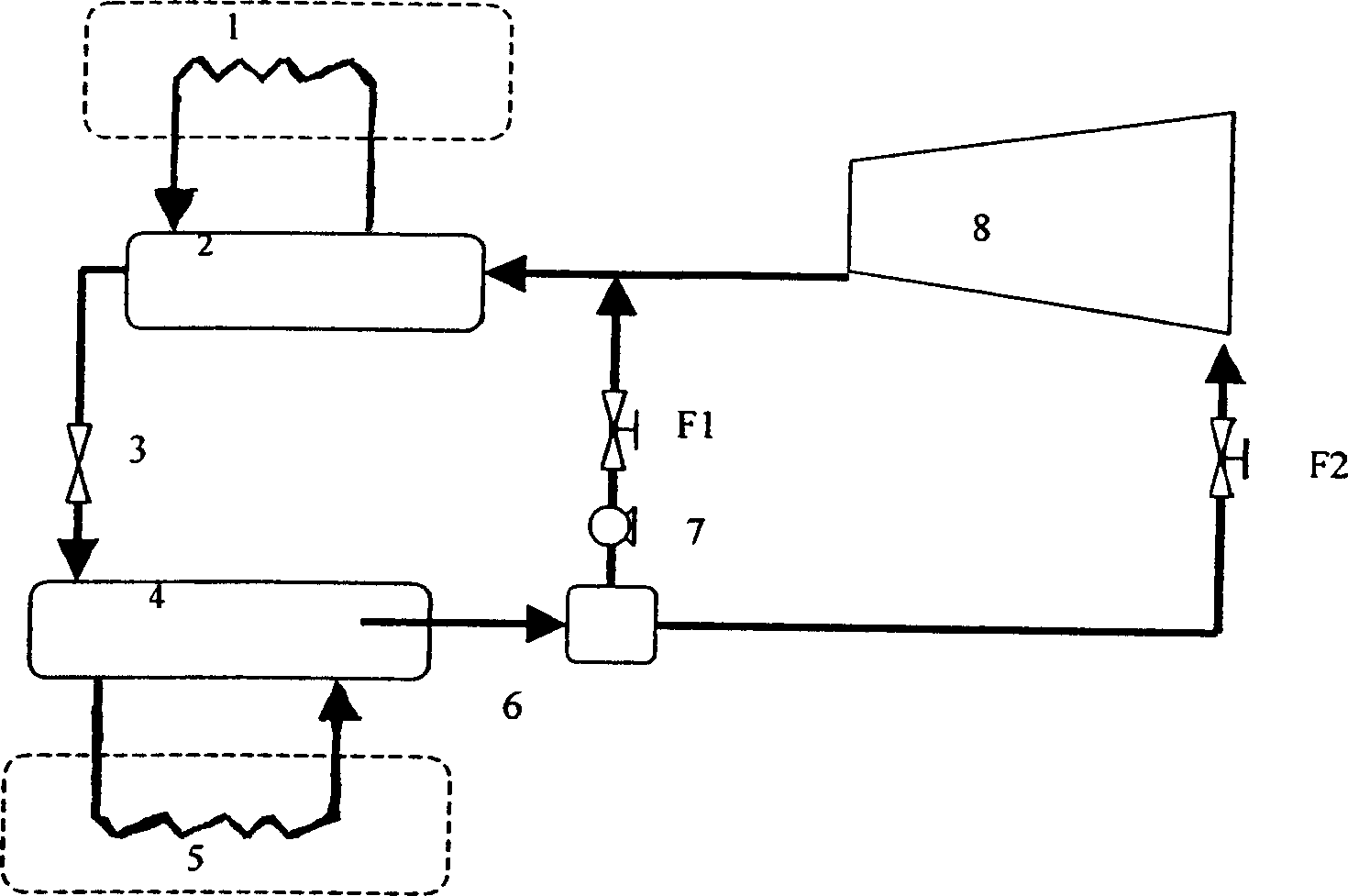
[0033] as attached figure 1As shown, the hydrate refrigeration system 12 is composed of a decomposition reactor (evaporator) 4, an expansion valve 3, a compressor 8, a formation reactor (condenser) 2, a gas-liquid separator 6, and a water pump 7. The decomposition reactor (evaporator) 4, the expansion valve 3, the compressor 8, the generation reactor (condenser) 2, the gas-liquid separator 6 and the water pump 7 are connected through pipelines, and the pipelines are equipped with hydrate refrigerant. The decomposition reactor (evaporator) 4 is directly connected to the cold end 5 for cooling. The generating reactor (condenser) 2 is directly connected to the hot end 1 to release heat to the outside. During operation, the compressor 8 compresses the gas to generate high-pressure gas, and the high-pressure gas reacts with water in the generating reactor (condenser) 2 to generate gas hydrate and release heat. Reactor (evaporator) 4, the hydrate is decomposed into gas and water ...

Embodiment 2

[0037] as attached figure 1 As shown, the hydrate refrigeration system 12 is composed of a decomposition reactor (evaporator) 4, an expansion valve 3, a compressor 8, a formation reactor (condenser) 2, a gas-liquid separator 6, and a water pump 7. The decomposition reactor (evaporator) 4, the expansion valve 3, the compressor 8, the generation reactor (condenser) 2, the gas-liquid separator 6 and the water pump 7 are connected through pipelines, and the pipelines are equipped with hydrate refrigerant. The decomposition reactor (evaporator) 4 is directly connected to the cold end 5 for cooling. The generating reactor (condenser) 2 is directly connected to the hot end 1 to release heat to the outside. During operation, the compressor 8 compresses the gas to generate high-pressure gas, and the high-pressure gas reacts with water in the generating reactor (condenser) 2 to generate gas hydrate and release heat. Reactor (evaporator) 4, the hydrate is decomposed into gas and water...


PUM


Abstract

The invention discloses a refrigerating method for using hydrate as working medium and relative air conditioner. Said method comprises: generating high-pressure gas; generating gas hydrate; the slurry hydrate via the expand valve is depressurized to be fed to the decompose reactor (evaporator); the hydrate is decomposed into gas and water to adsorb heat; the gas and water are separated in gas-liquid separator to be fed to the compressor or generate reactor (condenser) to complete the cycle. Said air conditioner comprises a decompose reactor (evaporator), a expand valve, a compressor, a generate reactor (condenser), a water pump, and a gas-liquid separator connected to the valve via tubes, while the tube is filled with hydrate refrigerating working medium; the decompose reactor (evaporator) is connected to the cold end; the generate reactor (condenser) is connected to the hot end to discharge heat outside the room. The invention can save energy with high efficiency and wider application.

Description

technical field [0001] The invention relates to refrigeration technology, in particular to a refrigeration method using gas hydrate as a working medium and an air-conditioning refrigeration device. technical background [0002] Gas hydrate is a foreign gas or volatile liquid combined with water to form a cage crystal compound. Water molecules form a lattice network to surround foreign molecules. In the lattice network, water molecules are combined with each other through hydrogen bonds, and foreign molecules and water molecules are attracted by Vander walls. An important feature of gas hydrate is that it can not only form below the normal freezing point of water, but also crystallize and solidify above the freezing point. Three crystal structures have been found so far, namely structure I, II and structure H-type hydrate. Common gas hydrates can be divided into three categories, one is refrigerant gas hydrate, the other is natural gas gas hydrate, and the other is CO 2 ga...

Claims


Application Information

Patent Timeline
IPC IPC(8): F25B23/00C09K5/16
Inventor 樊栓狮李栋梁梁德青杨向阳唐翠萍赵翔勇
Owner GUANGZHOU INST OF ENERGY CONVERSION - CHINESE ACAD OF SCI
Learn More