

Assembled uniform area light source
A surface light source and light source technology, applied in optics, optical components, nonlinear optics, etc., can solve problems such as unfavorable practicality, difficulty in uniform light emission, and reduced system efficiency
- Summary
- Abstract
- Description
- Claims
- Application Information
AI Technical Summary
Problems solved by technology
Method used
Image

Examples
Embodiment 1
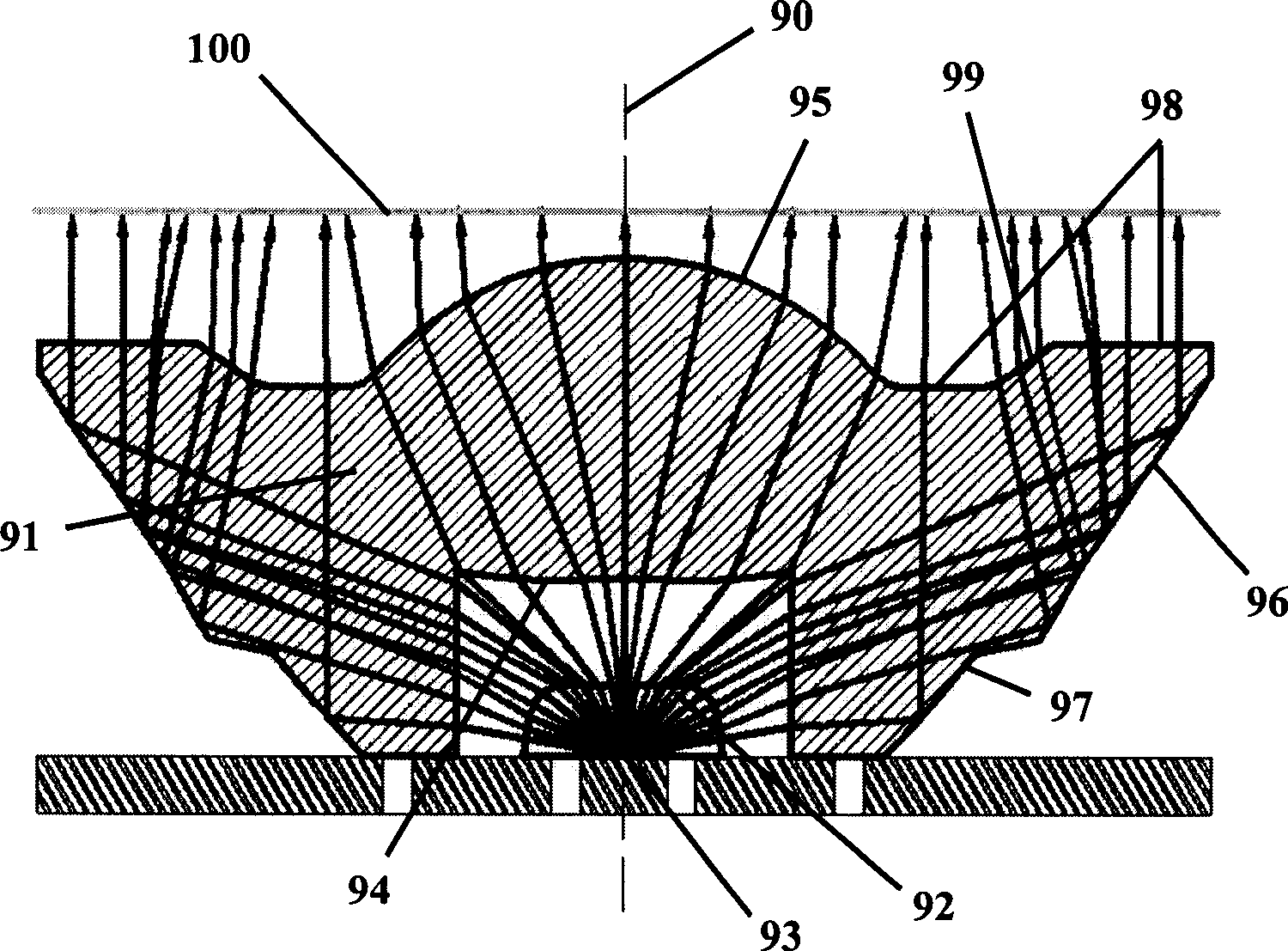
[0050] In the surface light source assembled based on light-emitting diodes in Embodiment 1, its surface light source module includes a light uniformity-collimation mechanism, that is, a light uniformity-collimation lens 91, such as figure 2 shown. In this embodiment, the light uniformity mechanism and the collimation mechanism are integrated, that is, the light uniformity-collimation lens 91 is used to replace the functions of the light uniformity mechanism and the collimation mechanism.
[0051] figure 2 It is the cross-sectional view and light path diagram of this surface light source module. The LED light source 93 is packaged with a lens 92 . The light emitted from the LED light source 93 is refracted by the lens 92 once, and then enters the homogenizing-collimating lens 91 . The curved surface 94 makes the light with a relatively small angle with the central axis 90 evenly distributed on the spherical surface 95, and collimates and exits through the spherical surfac...
Embodiment 2
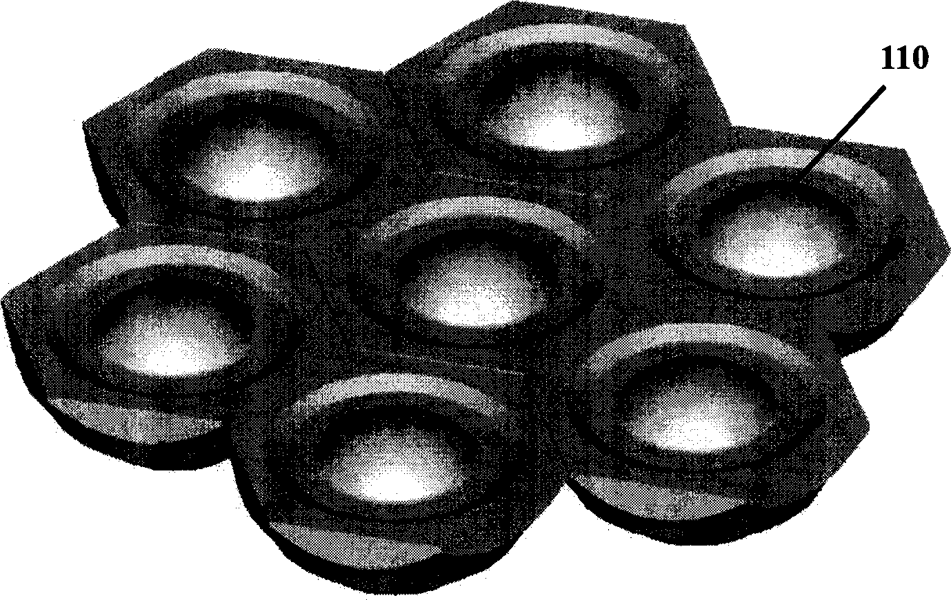
[0055] In the surface light source assembled based on light-emitting diodes in Embodiment 2, the surface light source module is another uniform light-collimation mechanism, that is, light uniform-collimator lens groups 120 and 122, such as Figure 6 shown. Here, the homogenizing-collimating lens groups 120 and 122 replace the functions of the homogenizing mechanism and the collimating mechanism. The light emitted from the LED light source 121 is uniformly and substantially collimated to the light exit plane 123 through a series of refraction and reflection on the surfaces of the lens groups 120 and 122 . This homogenization-collimation mechanism has a different form from that of Embodiment 1, but its working principle is similar, so it will not be repeated here.
[0056] The surface light source assembled from surface light source modules based on light-emitting diodes in Embodiment 2, its top view is as follows Figure 7 shown. 9 is a surface light source module, and its t...
Embodiment 3
[0058] Figure 8 It is a cross-sectional view and an optical path diagram of the surface light source module of Embodiment 3.
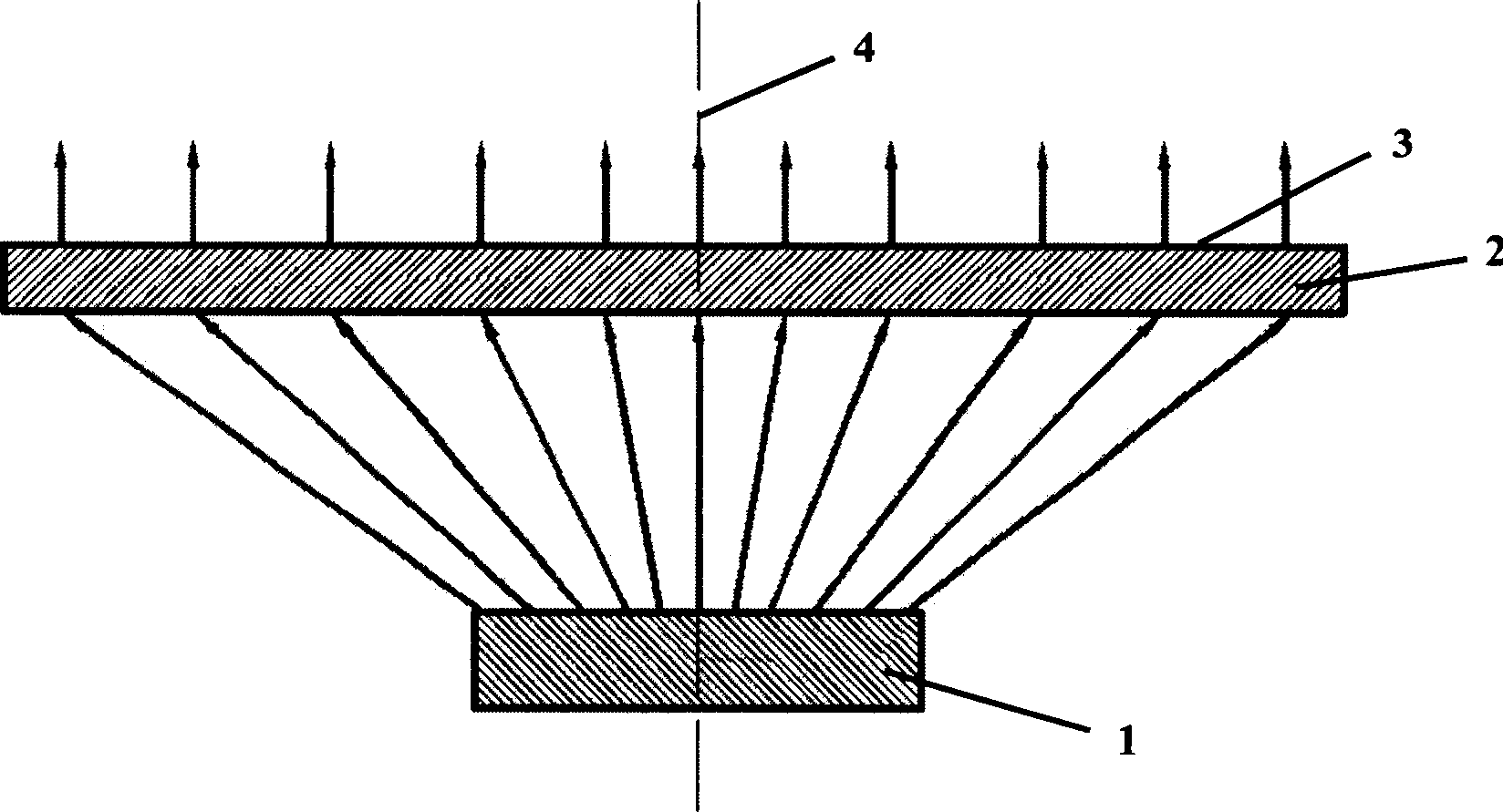
[0059] The dodging mechanism uses a dodging lens 23 to realize. The function of the spherical lens 22 is to encapsulate the LED light source 20 . The function of the homogenizing lens 23 is to refract the light emitted by the LED light source 20 through the ball lens 22, and then reorient it, and then undergo refraction or a series of refraction and total reflection in the homogenizing lens 23, so that it is in the surface light source module. An approximately uniform illuminance is generated on the light exit plane 12 , that is, the light is evenly distributed on the light exit plane 12 . In this embodiment, only one LED light source 20 is used, which is just for convenience of illustration, and does not limit the possibility of using multiple LED light sources.
[0060] The collimating mechanism is a collimating panel 24, the upper surface of whi...
PUM
 Abstract
Description
Claims
Application Information