Capacitor MEMS acceleration sensor

An acceleration sensor, capacitive technology, used in the measurement of acceleration, speed/acceleration/shock measurement, instruments, etc., can solve the problem of increasing the cost of the sensor, achieve the effect of simple structure, reduce production conditions and costs, and reduce damping

Active Publication Date: 2006-10-18
WEIHAI SUNFULL GEOPHYSICAL EXPLORATION EQUIP
View PDF0 Cites 18 Cited by
  • Summary
  • Abstract
  • Description
  • Claims
  • Application Information

AI Technical Summary

Problems solved by technology

This greatly increases the cost of the sensor

Method used


Image

  • Capacitor MEMS acceleration sensor

Examples


Embodiment Construction

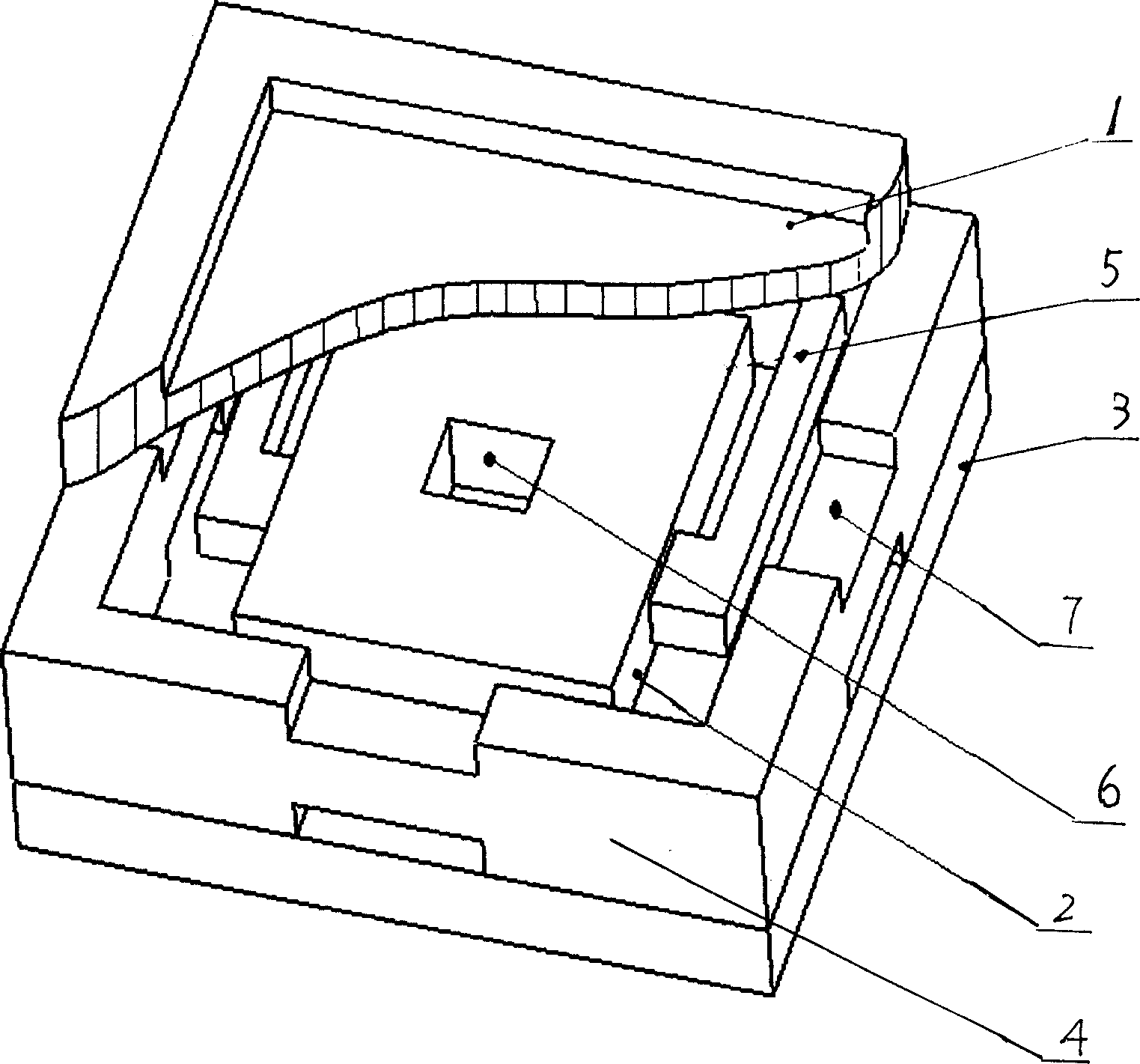
[0018] from figure 1 It can be seen that a capacitive MEMS acceleration sensor includes an upper electrode 1, a lower electrode 3 and a movable middle electrode. The middle electrode moves up and down under the action of acceleration, and together with the upper and lower electrodes forms a variable-pitch differential capacitor. The upper electrode 1 and the lower electrode 3 can be made of high silica glass or single crystal silicon. They are grooved electrodes formed by micromachining techniques. The upper electrode 1 and the lower electrode 3 also play the role of overload protection. The middle electrode is sandwiched between the upper electrode 1 and the lower electrode 3, which is based on single crystal silicon with [100] crystal orientation, and is formed by micromachining technology to form an integrated body including frame 4, mass block 2, cantilever beam 5, etc. Composite beam structure. The proof mass 2 is supported by a cantilever beam 5 and the like, and is ...


PUM


Abstract

The capacitor MEMS acceleration sensor is one sandwich type differential capacitor structure comprising an upper electrode, a middle electrode and a lower electrode, and the movable middle electrode includes one frame with slots, one mass block with one central hole and one cantilever beam. When the mass block moves up and down, the air inside the cavity may pass through the hole and flow out through the slots, and the enhanced air flow can prevent the mass block from moving freely, resulting low damp and less noise.

Description

technical field [0001] The invention relates to an earthquake sensing device, in particular to a capacitive MEMS acceleration sensor. Background technique [0002] Seismometers are commonly used in petroleum seismic exploration. The damping adjustment method is to add a damping ring or adjust the spring stiffness to adjust the spring stiffness, which will affect the sensitivity. Adding a damping ring is an effective method. When the coil moves in the magnetic field, a current is generated , and the damping ring generates a reverse magnetic field to prevent the coil from moving and play a damping role. [0003] The capacitive MEMS acceleration sensor includes an upper electrode, a lower electrode and a movable middle electrode. The upper electrode and the lower electrode are grooved electrodes formed by micromachining technology. The movable electrode and the upper and lower fixed electrodes form a sandwich structure. After the earthquake, the displacement of the central ele...

Claims


Application Information

Patent Timeline
Patent Type & Authority Applications(China)
IPC IPC(8): G01P15/125
CPCB81B3/0078B81B2201/0235G01P15/125G01P2015/0882
Inventor 颜永安于国良唐晓刚牛德芳赵冰孙中心星学奎张桂先张乐巧
Owner WEIHAI SUNFULL GEOPHYSICAL EXPLORATION EQUIP
Why Eureka
Try Eureka