Projection optical system and its imaging module and imaging method

A technology of projection optical system and imaging module, which is applied in the field of projection optical system and its imaging module and imaging, and can solve the problems of limited optical path distance, large volume, limited shape and volume of projection optical system, etc.

Inactive Publication Date: 2006-10-18
HONG FU JIN PRECISION IND (SHENZHEN) CO LTD +1
View PDF0 Cites 3 Cited by
  • Summary
  • Abstract
  • Description
  • Claims
  • Application Information

AI Technical Summary

Problems solved by technology

[0004] In order to achieve the above effects, the external volume of the known projection optical system is limited by the optical path distance and the structural cooperation between the imaging module 1a and the lens module 2a and is not easy to change
That is, the optical path distance is limited by the simple combination of traditional prism groups 12 (triangular prisms with multiple different angles) and the complex structure of traditional lens module 2a (coordination of multiple lens groups), and cannot be shortened.
[0005] In other words, in order to achieve a good projection effect, the known projection optical system is limited by the structural combination of the imaging module 1a and the lens module 2a and the influence of the optical path distance generated by the structural combination, and cannot reduce its original Due to the size of the existing projection optical systems on the market, although the reduction of other projection optical components has been revealed, the volume is still too large for users to easily carry and use
[0006] As can be seen from the above, the above-mentioned known projection optical system obviously has inconvenience and disadvantages in actual use, and needs to be improved.

Method used


Image

  • Projection optical system and its imaging module and imaging method
  • Projection optical system and its imaging module and imaging method
  • Projection optical system and its imaging module and imaging method

Examples


Embodiment Construction

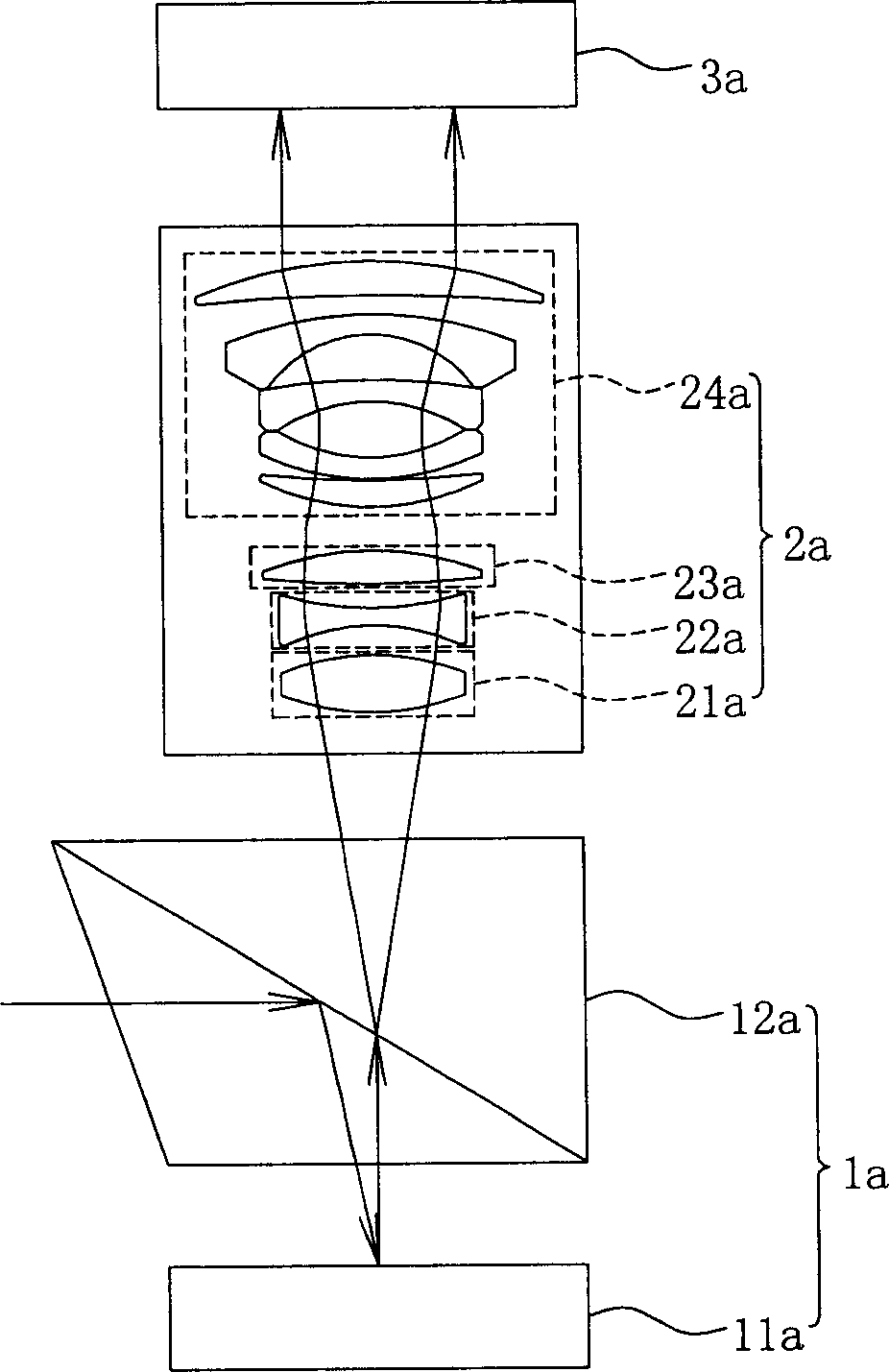
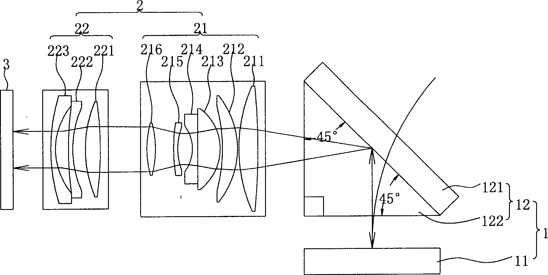
[0016] see image 3 As shown, it is a schematic diagram of the imaging module and the lens module of the projection optical system of the present invention. Depend on image 3 It can be seen that the present invention provides a projection optical system, which includes: an imaging module 1 and a lens module 2 .

[0017] Wherein, the imaging module 1 has a digital micromirror device 11 and a prism group 12 . The prism group 12 has an imaging error fine-tuning prism 121 and an isosceles triangular prism 122 cooperating with the digital micromirror device 11 . The three interior angles of the isosceles triangular prism 122 are 45 degrees, 45 degrees and 90 degrees, which are used to achieve the shortest optical path distance when the light beam is reflected. In addition, the prism group 12 is used to receive a light beam and allow the light beam to pass through, and deflect the light beam in a large arc, and the prism group 12 can project the transmitted light beam on the dig...


PUM


Abstract

The present invention is projection optical system and its imaging module and imaging method. The projection optical system has one imaging module comprising a imaging error trimming prism, a isosceles triangle prism and a digital micro lens unit and one lens module comprising two lens combinations in optimal arrangement, so that it has 50 % reduced size compared with common projection optical system. The reduced projection optical system is easy to carry and has short optical path and optimal projection effect.

Description

technical field [0001] The present invention relates to a projection optical system and its imaging module and imaging method, especially to a fine-tuning prism utilizing imaging errors, the cooperation of an isosceles triangular prism and a digital micromirror device, and an optimal arrangement and combination of two lens groups. In order to achieve the projection optical system with the shortest optical path and the best projection effect, its imaging module and imaging method. Background technique [0002] see figure 1 As shown, it is a schematic diagram of the cooperation of the imaging module and the lens module of the known projection optical system. Depend on figure 1 It can be known that the known projection optical system includes: an imaging module 1a and a lens module 2a. Wherein, the imaging module 1a includes a digital micromirror device 11a (Digital Micromirror Device, DMD) and a prism group 12a. The lens module 2a at least includes a first lens group 21a, ...

Claims


Application Information

Patent Timeline
Patent Type & Authority Applications(China)
IPC IPC(8): G02B27/18G03B21/00H04N5/74H04N9/31
Inventor 许健平陈嘉鸿
Owner HONG FU JIN PRECISION IND (SHENZHEN) CO LTD
Why Eureka
Try Eureka