A signal transmission optical module

A signal transmission and optical module technology, applied in the field of optical communication, can solve the problem that the packaging thickness does not meet the market demand for ultra-thin products, and achieve the effects of reduced thickness, high-efficiency heat dissipation, and small signal loss

Active Publication Date: 2022-04-22
HANGZHOU MO LINK TECH CO LTD
View PDF6 Cites 0 Cited by
  • Summary
  • Abstract
  • Description
  • Claims
  • Application Information

AI Technical Summary

Problems solved by technology

However, the packaging thickness of the existing optical modules does not meet the market demand for ultra-thin products. Based on the market demand, the present invention is proposed

Method used


Image

  • A signal transmission optical module
  • A signal transmission optical module
  • A signal transmission optical module

Examples


no. 1 example

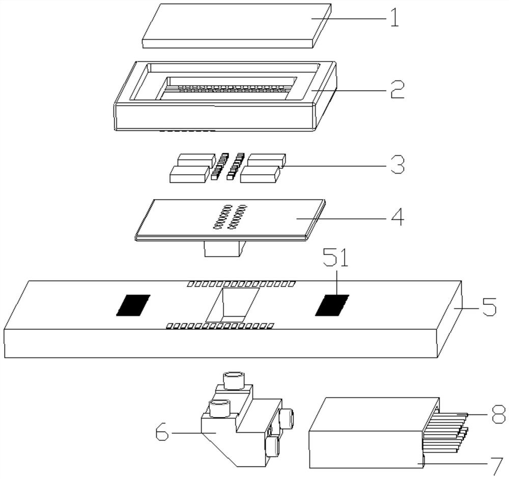
[0041] Such as Figure 9 As shown, the first lens module 4 is integrated with a first lens 9, and the optical fiber carrier 7 is integrated with a second lens 10. The light emitted by the photoelectric conversion chip 32 is collimated through the first lens 9 and passed through the second lens 10. The light received by the fiber group 8 is collimated by the second lens 10 and then focused onto the photoelectric conversion chip 32 by the first lens 9 . At this time, the fiber carrier 7 is perpendicular to the PCB board 5 .

no. 2 example

[0043] Such as Figure 8 As shown, the optical module also includes a second lens module 6, the lens area 41 is provided with a positioning hole 42, the second lens module 6 is assembled with the first lens module 4 through the positioning hole 42, and the first lens module 4 A first lens 9 is integrated on the top, and a 90-degree corner block 11 and a second lens 10 are integrated on the second lens module 6. The 90-degree corner block 11 is a right-angled triangular prism, and the planes of the first lens 9 and the second lens 10 are Respectively parallel to the two right-angled surfaces of the 90-degree corner block 11, so that the light collimated by the first lens 9 passes through the 90-degree corner block 11 and enters the second lens 10 after turning 90 degrees, and the light emitted by the photoelectric conversion chip 32 passes through the After the first lens 9 is collimated and turned by 90 degrees through the 90-degree corner block 11, it is focused into the opti...

no. 3 example

[0045] Such as Figure 8 As shown, the optical module also includes a second lens module 6, the lens area 41 is provided with a positioning hole 42, the second lens module 6 is assembled with the first lens module 4 through the positioning hole 42, and the first lens module 4 A first lens 9 is integrated on the top, a 90-degree corner block 11 is integrated on the second lens module 6, a second lens 10 is integrated on the optical fiber carrier 7, the 90-degree corner block 11 is a right-angled triangular prism, and the first lens 9 and The planes of the second lens 10 are respectively parallel to the two right-angle surfaces of the 90-degree corner block 11, so that the light collimated through the first lens 9 enters the second lens 10 after turning 90 degrees through the 90-degree corner block 11. This implementation Compared with the second embodiment, only the second lens 10 is separated from the second lens module 6, and the transmission principle of the optical path is ...


PUM


Abstract

A signal transmission optical module, including a PCB board and a first lens module, the first lens module is placed in a structural frame, a transmission line is arranged inside the structural frame, the transmission line is connected to a chipset, and a lead is provided on the PCB board. The pin group, the pin group is connected with the transmission line, and the optical signal transmission is realized through the lens module between the optical fiber group and the photoelectric conversion chip. Part of the thickness of the first lens module is embedded in the through groove of the PCB board, so that the overall thickness of the optical module is reduce. The overall thickness of the optical module of the present invention is equivalent to the sum of the thicknesses of the structural frame, the PCB board and the optical fiber carrier, the electrical signal transmitted from the interface on the PCB board is transmitted to the drive chip through the transmission line, and the photoelectric conversion chip realizes photoelectric conversion, and the optical signal Passing through the first lens module and the second lens module in turn, the transmission optical path is short, the signal can be transmitted with low loss, and the upper or lower surface of the structure can be in contact with the shell directly or through thermal conductive adhesive, which is conducive to high-efficiency heat dissipation.

Description

technical field [0001] The invention relates to the technical field of optical communication, in particular to an optical module for signal transmission. Background technique [0002] The optical transceiver integrated module, referred to as optical module or optical fiber module, is an important part of the optical fiber communication system. It is composed of optoelectronic devices, functional circuits and optical interfaces. The optoelectronic devices include two parts: transmitting and receiving. For optical signals, the receiving end converts the optical signal into an electrical signal. Simply put, the function of the optical module is to convert the electrical signal into an optical signal at the transmitting end. After transmission through the optical fiber, the receiving end converts the optical signal into an electrical signal. The packaging method and signal transmission method of optical modules determine the size and signal quality of the entire optical module. ...

Claims


Application Information

Patent Timeline
Patent Type & Authority Patents(China)
IPC IPC(8): G02B6/42
CPCG02B6/428G02B6/4204G02B6/4272
Inventor 王灏秦海棠莫程智
Owner HANGZHOU MO LINK TECH CO LTD
Why Eureka
Try Eureka