WDM demultiplexer based on film interference filter

A demultiplexer and thin-film interference technology, which is applied in the field of physical optics and optical fiber communication passive devices, can solve the problems of not being able to make full use of the optical path of 3D space light waves, large linear dimensions occupied in the lateral direction, and long collimation distances, etc., to achieve Effects of compact structure, easy coupling, and compact device width

Pending Publication Date: 2020-07-24
南京光通光电技术有限公司
View PDF0 Cites 0 Cited by
  • Summary
  • Abstract
  • Description
  • Claims
  • Application Information

AI Technical Summary

Problems solved by technology

[0003] Purpose of the present invention: to overcome the fact that the horizontal dimension of the device is much larger than the vertical dimension, the 3D space cannot be fully utilized and the optical path of the last em

Method used


Image

  • WDM demultiplexer based on film interference filter
  • WDM demultiplexer based on film interference filter
  • WDM demultiplexer based on film interference filter

Examples


Embodiment 1

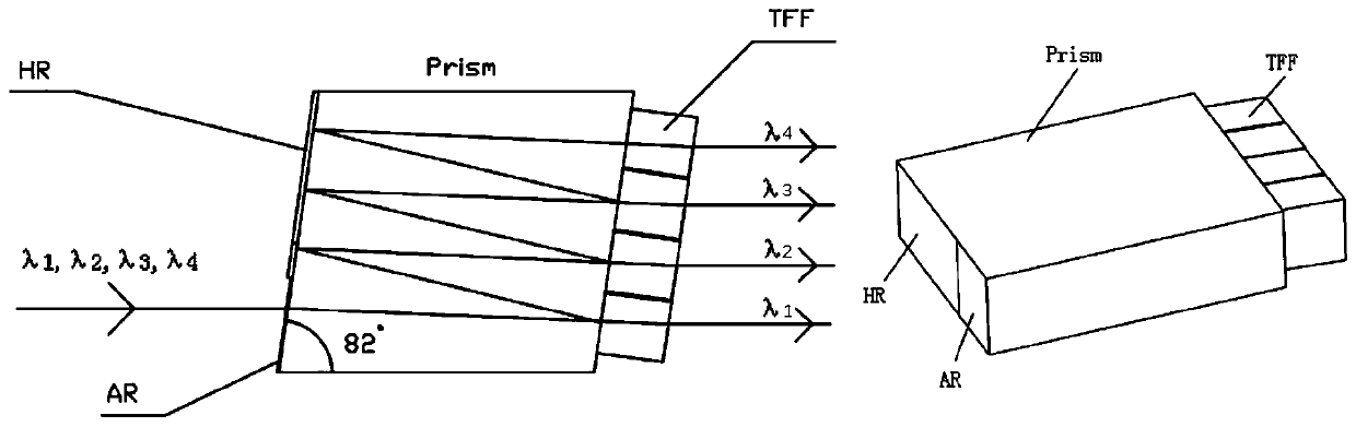
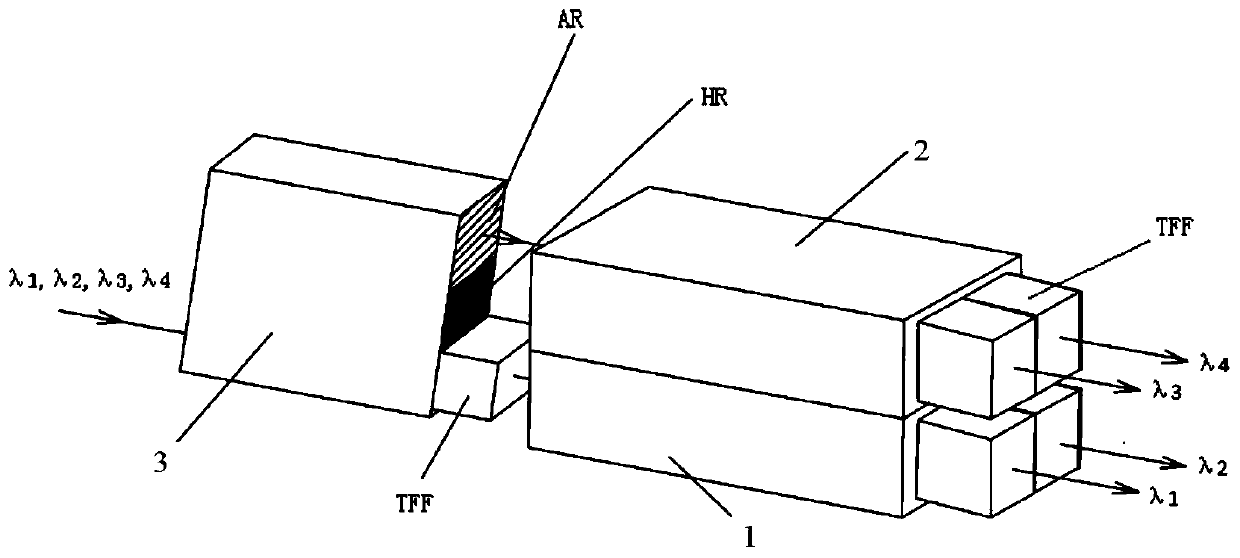
[0027] image 3 It is a schematic diagram of the structure and geometric configuration of the four-wave WDM demultiplexer based on the thin-film interference filter of the present invention, which is composed of three prisms, namely the first prism 1, the second prism 2 and the third prism 3, and the first prism 1 and the width of the second prism 2 is figure 1 Half of the prisms used in existing four-wave WDM demultiplexers, with the same length and height as figure 1 consistent. The beam entrance of the front plane of the first prism 1, the second prism 2 and the third prism 3 is provided with an anti-reflection coating area AR, and the rest is a high reflection film area HR, and the third prism 3 is located at the output port on the upper part of the rear end plane. There is an anti-reflection coating area, and the part between the upper output port and the lower output port is a high-reflection coating area. Two narrow strips are attached to the output ports of the first...

Embodiment 2

[0034] In this embodiment, the first prism 1 and the second prism 2 can be combined into a prism with a thickness of 2 mm, and the corresponding narrow-band thin-film interference filter TFF is appropriately pasted on its output port, and the 2 mm thick prism can play a role. It has the same function as the first prism 1 and the second prism 2, but the assembly is easier.

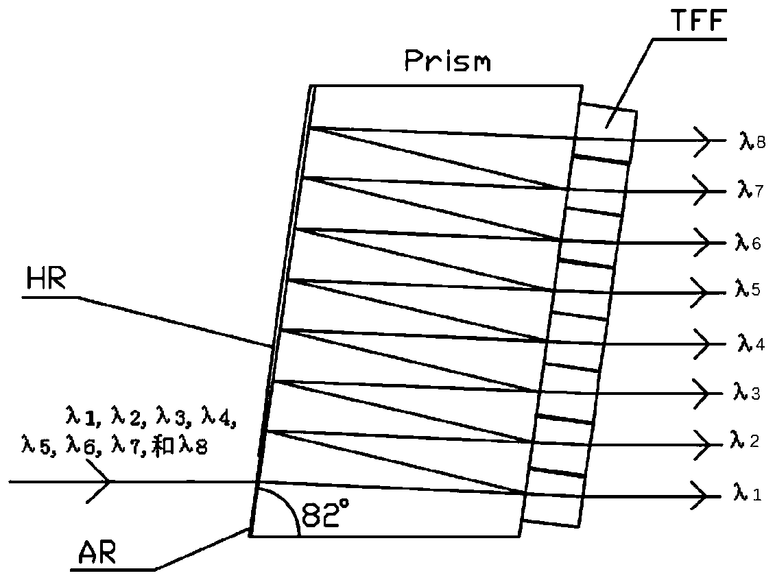
[0035] If the first prism 1 and the second prism 2 are two-wave, then the demultiplexer of the present invention is a four-wave demultiplexer, if the first prism 1 and the second prism 2 are four-wave, then this The inventive demultiplexer can be an eight-wave demultiplexer. from Figure 7 It can be seen that the four-wave device WDM demultiplexer (DeMUX) based on the thin film interference filter of the present invention can be easily extended to eight waves, and the demultiplexer (DeMUX) of the present invention is better than the existing demultiplexer The device (DeMUX) is much more compact, and the o...


PUM


Abstract

The invention discloses a WDM demultiplexer based on a film interference filter. The WDM demultiplexer comprises a preceding-stage demultiplexer and a backward-stage demultiplexer, and the preceding-stage demultiplexer is arranged in front of a light beam incident port of the backward-stage demultiplexer; and the preceding-stage demultiplexer divides an incident light beam into an upper beam of light waves with a front half wavelength and a lower beam of light waves with a rear half wavelength correspondingly. When the upper beam of light waves and the lower beam of light waves are emitted inparallel, an up-and-down distance exists; the backward-stage demultiplexer is used for carrying out re-wave-dividing on the incident upper and lower beams of light waves; and the extensibility of a three-dimensional space in each direction is fully utilized, so that the demultiplexer (DeMUX) can be made more compact, light paths of some channels are relatively shortened, devices are convenient tocouple, and the demultiplexer with more wavelength channels can be better manufactured.

Description

technical field [0001] The invention relates to the technical field of physical optics and optical fiber communication passive devices, in particular to a WDM demultiplexer based on thin-film interference filters. Background technique [0002] Wavelength division multiplexing (WDM) technology has been widely used in optical fiber transmission systems and optical network systems. This technology uses a single optical fiber to transmit multiple optical carriers of different wavelengths, making full use of the optical fiber bandwidth, so that the amount of information transmitted by the optical fiber can be greatly improved. Multiplication thus greatly reduces the cost of optical fiber transmission. The key components used in this wavelength division multiplexing (WDM) technology are optical wavelength multiplexers and demultiplexers; as far as optical wavelength demultiplexers are concerned, the most mature ones are based on Demultiplexer for Thin Film Interference Filter (TFF...

Claims


Application Information

Patent Timeline
IPC IPC(8): G02B6/293
CPCG02B6/29362
Inventor 张耐
Owner 南京光通光电技术有限公司
Why Eureka
Try Eureka