Projection LCD

A liquid crystal projection and display technology, which is applied to instruments, optics, nonlinear optics, etc., can solve the problems of light loss, the development trend of unfavorable miniaturization of devices, and the bulky volume of three-piece reflective liquid crystal projection systems. Efficiency, improving display quality and brightness, simplifying the effect of optical systems

Inactive Publication Date: 2006-10-18
CHUNGHWA PICTURE TUBES LTD
View PDF0 Cites 10 Cited by
  • Summary
  • Abstract
  • Description
  • Claims
  • Application Information

AI Technical Summary

Problems solved by technology

Therefore, the light with a certain polarization direction passes through the polarizer 240, while the light with another polarization direction cannot pass through, but the utilization efficiency of the light is not high.
[0006] Based on the above, because the light splitting and combining process in the three-chip reflective LCD projection system is too complicated, it will lead to the loss of light and affect the brightness and other optical performances of the LCD projector.
In addition, the volume of the three-chip reflective liquid crystal projection system is too large, which is not conducive to the development trend of device miniaturization
In addition, in the single-chip reflective liquid crystal projection system, since only about half of the light can pass through the polarizer, the light utilization efficiency of the entire system is greatly reduced.

Method used


Image

  • Projection LCD
  • Projection LCD
  • Projection LCD

Examples


no. 1 example

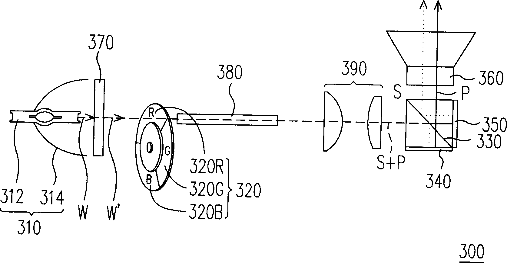
[0066] image 3 It is a schematic diagram of a liquid crystal projection display according to the first embodiment of the present invention. Please refer to image 3 , the liquid crystal projection display 300 mainly includes a light source 310 , a color wheel 320 , a polarization beam splitter 330 , two spatial light modifiers 340 , 350 and a projection lens 360 .

[0067] Such as image 3 As shown, the light source 310 includes, for example, a bulb 312 and a reflector 314 , and the white light W emitted by the bulb 312 is concentrated by the reflector 314 and emitted outward. The color wheel 320 is disposed on the light path of the white light W for converting the white light W into colored light such as red, green or blue. In a preferred embodiment of the present invention, the color wheel 320 has, for example, a red filter 320R, a green filter 320G, and a blue filter 320B. When the white light W passes through the color wheel 320 , the red light R passes through the in...

no. 2 example

[0079] Figure 8 It is a schematic diagram of a liquid crystal projection display according to the second embodiment of the present invention. Please refer to Figure 8 , the liquid crystal projection display 400 and the liquid crystal projection display 300 have similar or identical optical components marked with the same reference numerals, which include a light source 310, a color wheel 320, a polarization beam splitter 330, a spatial light modulator 340, 350 and a projection lens 360. In the second embodiment of the present invention, for example, the liquid crystal projection display 400 further includes optical components such as an invisible light filter 370 , a plurality of lenses 385 , and a converging lens 390 . Wherein, a plurality of lenses 385 are disposed on the optical path of white light or colored light between the light source 310 and the polarized beam splitter 330 . The arrangement and working principle of the above-mentioned optical elements are similar...


PUM


Abstract

The projection LCD includes a light source, a color wheel, a polarized light beam separator, a first space light modulator, a second space light modulator and a projecting lens. The white light the light source emits is converted in the color wheel into color light, the color light is split in the polarized light beam separator into one first color light and one second color light in different polarization directions, and the first color light and the second color light leave from the polarized light beam separator in different direction. Then, the first color light and the second color light are modulated separately in the first space light modulator and the second space light modulator before being reflected back to the polarized light beam separator. The projecting lens is set in the light path of the modulated first color light and second color light after the polarized light beam separator to project the modulated first color light and second color light to form image.

Description

technical field [0001] The invention relates to a projection display device, and in particular to a liquid crystal projection display. Background technique [0002] With the development of video technology, liquid crystal display technology has gradually been widely used in daily life, such as LCD TV, notebook computer (Notebook) or desktop computer LCD screen (Liquid Crystal Display, LCD), and LCD projector etc. Among them, LCD projector is one of the important technologies for large-size screen display. The structure of the liquid crystal projector can be mainly divided into the lighting part, the color separation part and the imaging part. [0003] figure 1 is a schematic diagram of a known three-chip reflective liquid crystal projection system, and figure 2 It is a schematic diagram of a known single-chip reflective liquid crystal projection system. Such as figure 1 As shown, the three-chip reflective liquid crystal projection system 100 includes a light source 11...

Claims


Application Information

Patent Timeline
IPC IPC(8): G03B21/14G02B27/18G02F1/13G03B21/00
Inventor 陈庆仲吴世民杨景安刘梅
Owner CHUNGHWA PICTURE TUBES LTD
Why Eureka
Try Eureka