
Multifunctional pneumatic conveying device

A pneumatic conveying and multi-functional technology, which is used in conveying bulk materials, conveyors, transportation and packaging.

Inactive Publication Date: 2006-10-25
NANJING ZIDONG INTELLIGENT TECH CO LTD
View PDF0 Cites 17 Cited by
  • Summary
  • Abstract
  • Description
  • Claims
  • Application Information

AI Technical Summary

Problems solved by technology

[0003] The commonly used weighing devices, drying devices, and mixing devices on the conveying device all use separate power sources, and sometimes have to be equipped with separate storage hoppers (bins), control devices, etc., the structure is very complicated, and the site occupied is large.

Method used


Image

  • Multifunctional pneumatic conveying device

Examples


Embodiment Construction

[0011] The present invention will be described in further detail below in conjunction with the accompanying drawings and embodiments.

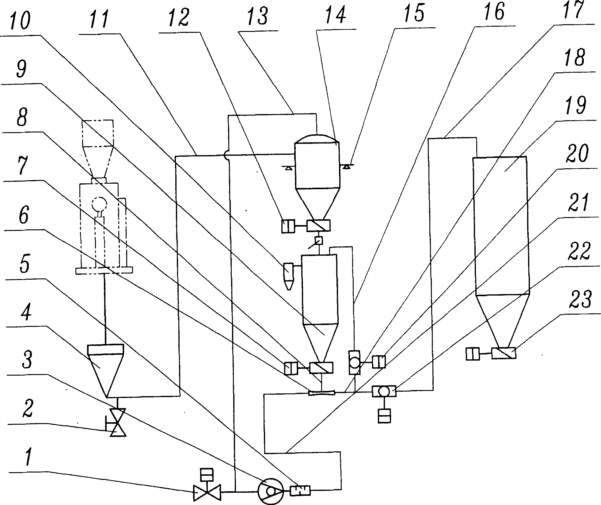
[0012] Such as figure 1 As shown, a multifunctional pneumatic conveying device includes a storage hopper 4, a receiving hopper 14, a storage bin 19 and a fan 3. The outlet of the storage bin 19 is provided with a storage bin discharge valve 23, and the storage hopper 4 passes through The material suction pipe 11 communicates with the hopper 14, the material suction pipe 11 is provided with a feed air valve 2, the hopper 14 is connected with the fan 3 through the suction pipe 13, and the discharge port of the hopper 14 is provided with a hopper discharge port. Valve 12, intermediate feed bin 9 with air outlet device 10 is arranged below receiving hopper 14, and the feed port of intermediate feed bin 9 communicates with the discharge port of receiving hopper 14 through material pipe, and the discharge of intermediate feed bin 9 The middle silo ...


PUM


Abstract

A multifunction air conveyer includes the storage hopper, the material receiving hopper, the storage barn and the fan. The intermediate barn with the air-out device which is connected to the feeding mixer by the discharge nozzle and the valve which is connected to the fan by the air pipe is set in the bottom of the receiving hopper. The valve is connected to the storage barn. The circulating pipe with the circulating valve is connected to the intermediate barn. The invention use the fan as the power source, it not only delivery the material by the suction pressure but the positive pressure or the both pressure. It also can mix the material in the mode of the external circulating by the positive pressure.

Description

technical field [0001] The invention relates to a multifunctional pneumatic conveying device, especially a conveying device for powder and granular material, which is applied in industries such as electric power, chemical industry, pharmacy, petrochemical, magnetic material, food and feed. Background technique [0002] At present, the pneumatic conveying devices used in many industries convey materials, either using negative pressure or positive pressure, and most of them use a fan to generate air pressure to convey a material. It is rare to use negative pressure and positive pressure on one device at the same time, and often only the same material (material characteristics are the same) can be transported. [0003] The commonly used weighing devices, drying devices, and mixing devices on the conveying device all use separate power sources, and sometimes have to be equipped with separate storage hoppers (bins), control devices, etc. The structure is very complicated and take...

Claims


Application Information

Patent Timeline
Patent Type & Authority Applications(China)
IPC IPC(8): B65G53/04B65G53/34
Inventor 刘建平高文海虞兰剑校亚
Owner NANJING ZIDONG INTELLIGENT TECH CO LTD
Learn More