Hollow part electroforming furrow filling method

A filling method and groove technology, applied in the direction of electroforming, electrolysis, etc., can solve the problems of dimensional accuracy distortion, low film conductivity, etc., and achieve the effect of high smoothness and dimensional accuracy, good conductivity, and easy dissolution

Active Publication Date: 2006-10-25
NANJING UNIV OF AERONAUTICS & ASTRONAUTICS
View PDF0 Cites 3 Cited by
  • Summary
  • Abstract
  • Description
  • Claims
  • Application Information

AI Technical Summary

Problems solved by technology

The conductivity of the film obtained by graphitization is low. Although the conductivity of

Method used


Image

  • Hollow part electroforming furrow filling method
  • Hollow part electroforming furrow filling method

Examples


Example Embodiment

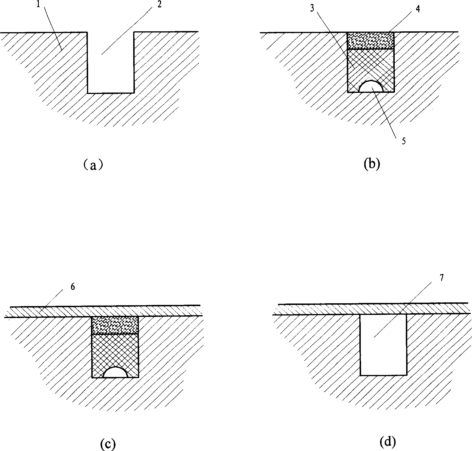
[0020] Implement the operation process of the present invention——"the method for filling grooves in the electroforming of hollow parts", such as figure 1 As shown, it is characterized in that the filler in the groove is divided into two layers, namely the bottom layer (3) and the conductive layer (4), and there are preformed liquid holes (5) in the bottom layer.

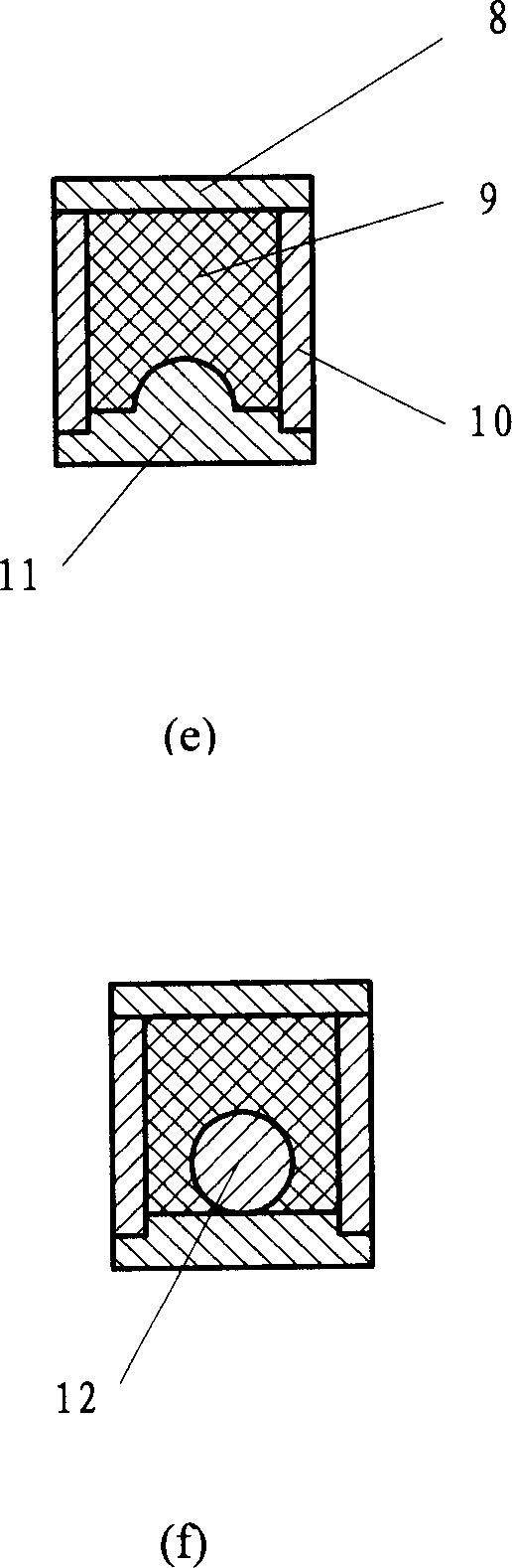
[0021] figure 2 Shown is a schematic diagram of the auxiliary tool for preforming the bottom material, through the combination of the bottom plate (11), side plate (10) and top plate (8), the same structure as the groove (2) on the part is formed for the bottom material preformed. It is characterized in that there is a semicircular or nearly semicircular protrusion on the inner side of the bottom plate (11), which is used for the pre-forming of the liquid hole (5). Above-mentioned protrusion also can be replaced with the material that is bonded on the bottom of base plate (11) circular or nearly circular circular ...


PUM


Abstract

The filling method of the groove during the electroforming of the hollow part belongs to the domain of the electroform process. The filling of the grove is performed twice layers respectively: the first layer chooses the diffluent plastic to be the bottom layer (3); the second layer adopts the homogeneity plastic mixing with the certain percent of the metal powder, the layer is served as the electric layer (4), it has the good capability of conducting and engine machining. If the hole passing the liquid used for washing is obligated on the bottom of the first material, the filling material after the electroforming can be dissolved to wipe off better. The invention is fit for the mallow parts, especially, it is fit for the thin route to fill the grove before the electroforming and wipe off the filling material after the electroforming. The process is easy. The period of filling and pulling off the model is short. The core model produced by the invention has many merits such as the low size precision, the good electric ability and without the remaining filling material after the pulling off the model.

Description

technical field [0001] The invention relates to a method for filling grooves in electroforming of hollow parts, belonging to the field of electroforming. Background technique [0002] With the development of modern industry and technology, many special-shaped and precision metal parts that are difficult to be processed by traditional methods have appeared, such as rocket engine combustion chambers and other hollow parts with complex channels or cavities. At present, the forming of the above-mentioned hollow parts is often carried out in two steps: firstly, the cavity or channel part is processed into an open groove shape by traditional processing methods, and then the part shell is produced by electroforming technology. Before performing electroforming, an important step is to fill the trench with a material to join the trench walls and ensure the shape and size of the cavity or channel in the part. The material for filling the trench is required to have the following chara...

Claims


Application Information

Patent Timeline
IPC IPC(8): C25D1/10
Inventor 朱增伟朱荻曲宁松
Owner NANJING UNIV OF AERONAUTICS & ASTRONAUTICS
Why Eureka
Try Eureka