Semiconductor device and temperature detection method using the same

A technology of semiconductors and equipment, applied in the field of temperature detection, can solve the problems of output characteristic configuration and operation adjustment of temperature detection equipment, fluctuation of resistance temperature characteristics, etc., and achieve the effect of high small semiconductor device and high temperature detection sensitivity

Inactive Publication Date: 2006-10-25
FUJI ELECTRIC DEVICE TECH CO
View PDF2 Cites 4 Cited by
  • Summary
  • Abstract
  • Description
  • Claims
  • Application Information

AI Technical Summary

Problems solved by technology

When a resistor is used for temperature detection, usually when its detection sensitivity is made high, many significant fluctuations will occur in the temperature characteristic of the resistor due to its production
[0014] The semiconductor device disclosed in Patent Document 2 and the temperature sensor disclosed in Patent Document 3 use a diode for a temperature detection device, however, Patent Documents 2 and 3 do not provide any information for obtaining an output characteristic suitable for a temperature detection device. Detailed configuration and operational adjustments make any description

Method used


Image

  • Semiconductor device and temperature detection method using the same
  • Semiconductor device and temperature detection method using the same
  • Semiconductor device and temperature detection method using the same

Examples


no. 1 example

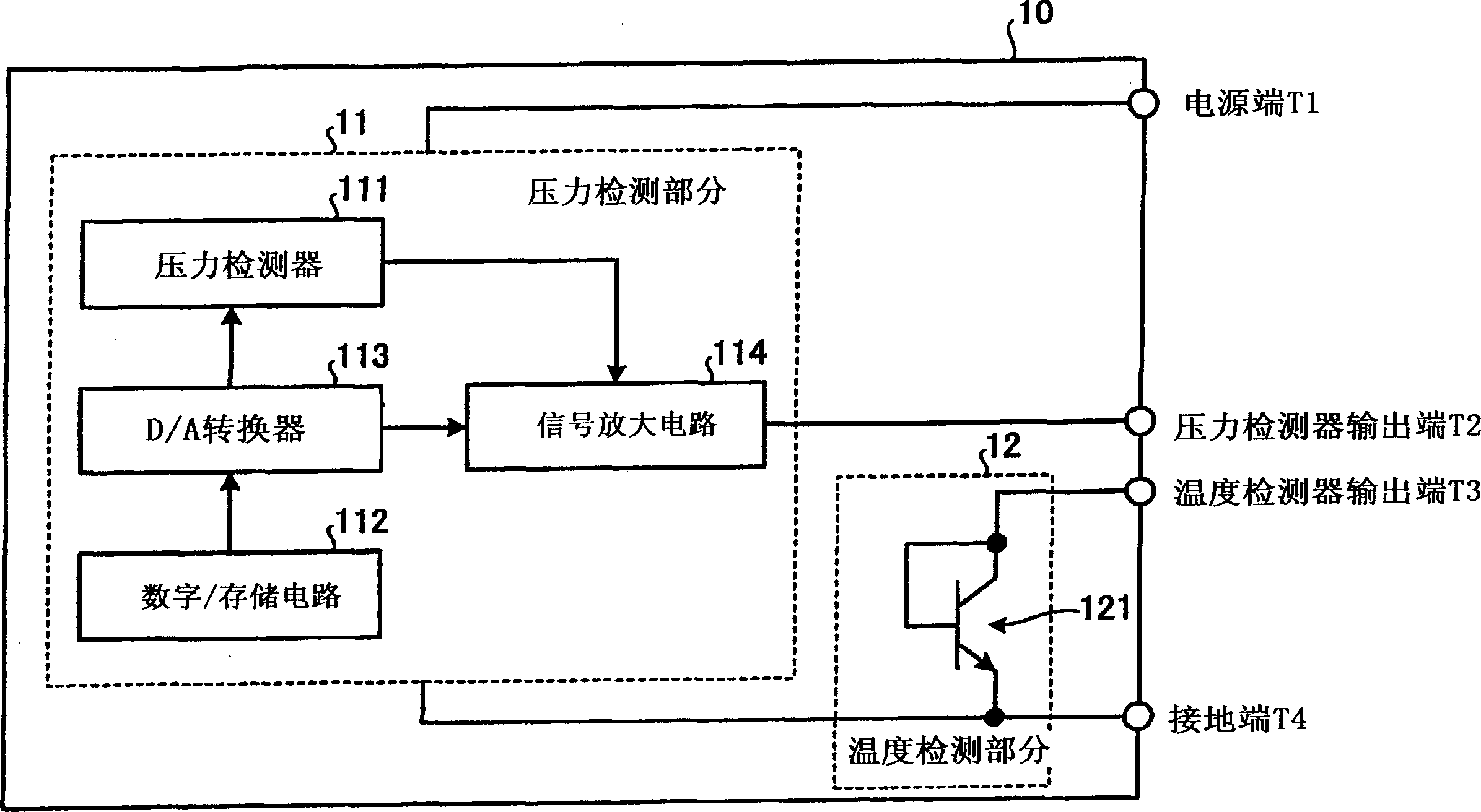
[0059] First, a semiconductor device according to a first embodiment of the present invention will be described. figure 1 is a block diagram of the semiconductor device according to the first embodiment. The semiconductor device 10 according to the first embodiment includes a pressure detection portion 11 disposed on the substrate, a temperature detection portion 12 disposed on the substrate, a power supply terminal T1, a pressure detection output terminal T2, a temperature detection output terminal T3, and a ground Terminal T4. The pressure detection section 11 includes a pressure detector 111 , a digital / storage circuit 112 , a D / A converter 113 , and a signal amplification circuit 114 .

[0060] The pressure detector 111 in the pressure detection part 11 detects pressure and outputs the detected pressure in the form of an electric signal. The digital / storage circuit 112 stores correction data for correction of sensitivity, offset, and temperature characteristics, and fee...

no. 2 example

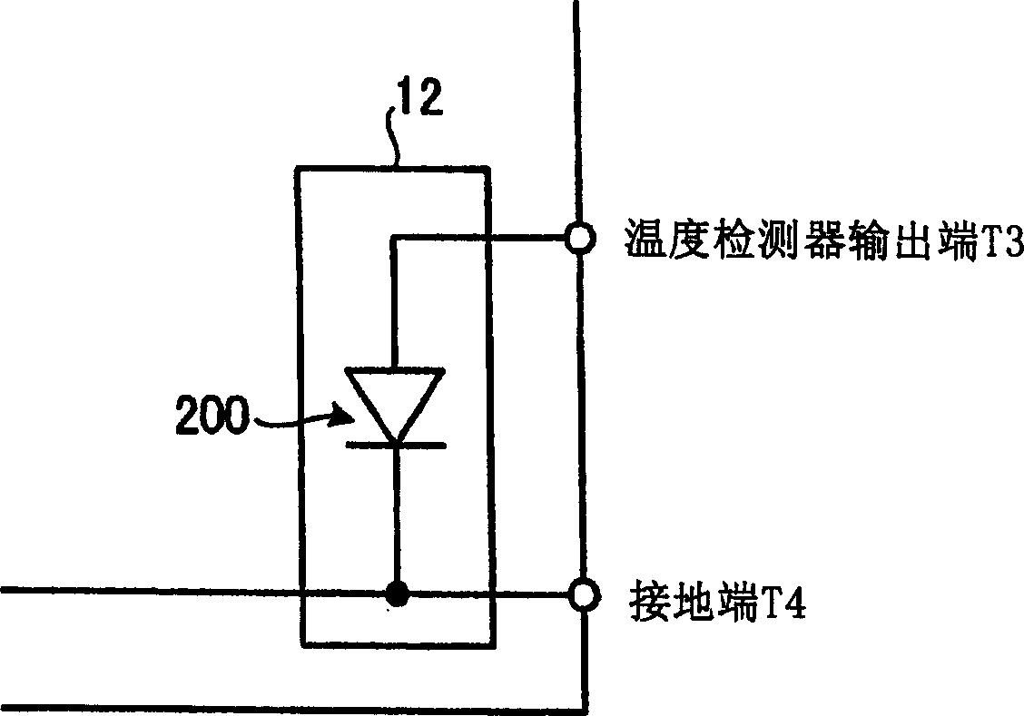
[0103] A semiconductor device according to a second embodiment of the present invention will be described below. Figure 13 is a block diagram of a semiconductor device according to a second embodiment of the present invention. The semiconductor device 20 according to the second embodiment differs from the semiconductor device 10 according to the first description in that the temperature detection section 12 in the semiconductor device 20 has a different structure from that in the semiconductor device 10, and in the semiconductor device 12 according to the second embodiment In the semiconductor device 20, the Zener diode 13 is connected between the temperature detection output terminal T3 and the ground terminal T4.

[0104] Figure 13 The temperature detection section 12 includes npn transistors 121 , 122 , 123 , 124 , and 125 . The npn transistors 121 to 125 may be connected such that respective bases and respective collectors are shorted to each other. In other words, ...


PUM


Abstract

A semiconductor device 10 according to the present invention includes a temperature detection section 12 that performs temperature detection with a semiconductor device formed in a semiconductor substrate; a sensor output terminal T3; a current generating part 21 connected to the output terminal T3, which applies a driving current to the temperature detecting part 12; and a voltage measuring device 22 connected to the output terminal 22, when the driving current of a predetermined value is When the current generating part 21 is supplied to the temperature detecting part 12, the voltage measuring means 22 measures the voltage of the output terminal T3 to perform temperature detection. A semiconductor device according to the present invention has a structure that contributes to its size reduction. The semiconductor device according to the present invention contributes to its easy production at low production cost. The temperature detection method according to the invention contributes to very precise operation of the semiconductor device.

Description

technical field [0001] The present invention relates to a semiconductor device performing pressure detection and temperature detection mainly for controlling an engine of an automobile or a motorcycle. The invention also relates to a temperature detection method. Background technique [0002] Detection of internal engine pressure and temperature for a car or motorcycle is essential for controlling the engine. Figure 14 is a cross-sectional view schematically showing a car engine facing as Figure 14 The basic behavior of the engine 40 shown in . First, air enters the cylinder 49 through the intake pipe 44 . Fuel is injected from fuel injection 46 and enters cylinders 49 of engine 40 together with air flowing through intake manifold 44 . [0003] In cylinder 49, piston 50, valve 47, and spark plug 48 repeat a series of actions consisting of intake air, compression, combustion (ignition and expansion), and exhaust (exhaust gas) in synchronization with each other so that eng...

Claims


Application Information

Patent Timeline
Patent Type & Authority Applications(China)
IPC IPC(8): F02D35/00H01L21/822
CPCG01K7/01G01K2205/02H01L27/092H01L2924/0002H01L2924/00B44C5/0446C09D5/08C09D5/16C09D133/00C09D163/00G09F19/22
Inventor 西川睦雄上柳胜道
Owner FUJI ELECTRIC DEVICE TECH CO
Why Eureka
Try Eureka