Method for moniforing receiving-end data-receiving condition by sending-end

A technology for receiving data and sending data, which is applied in the field of monitoring data reception at the sending end, which can solve the problem that the sending end cannot know the receiving data of the receiving end in time, and achieve the effect of effective control

Inactive Publication Date: 2006-10-25
HUAWEI TECH CO LTD
View PDF0 Cites 2 Cited by
  • Summary
  • Abstract
  • Description
  • Claims
  • Application Information

AI Technical Summary

Problems solved by technology

[0009] What the present invention aims to solve is the problem that in the prior art, the originating end cannot know the data receiving situation of the receiving end in time

Method used


Image

  • Method for moniforing receiving-end data-receiving condition by sending-end
  • Method for moniforing receiving-end data-receiving condition by sending-end

Examples


Embodiment Construction

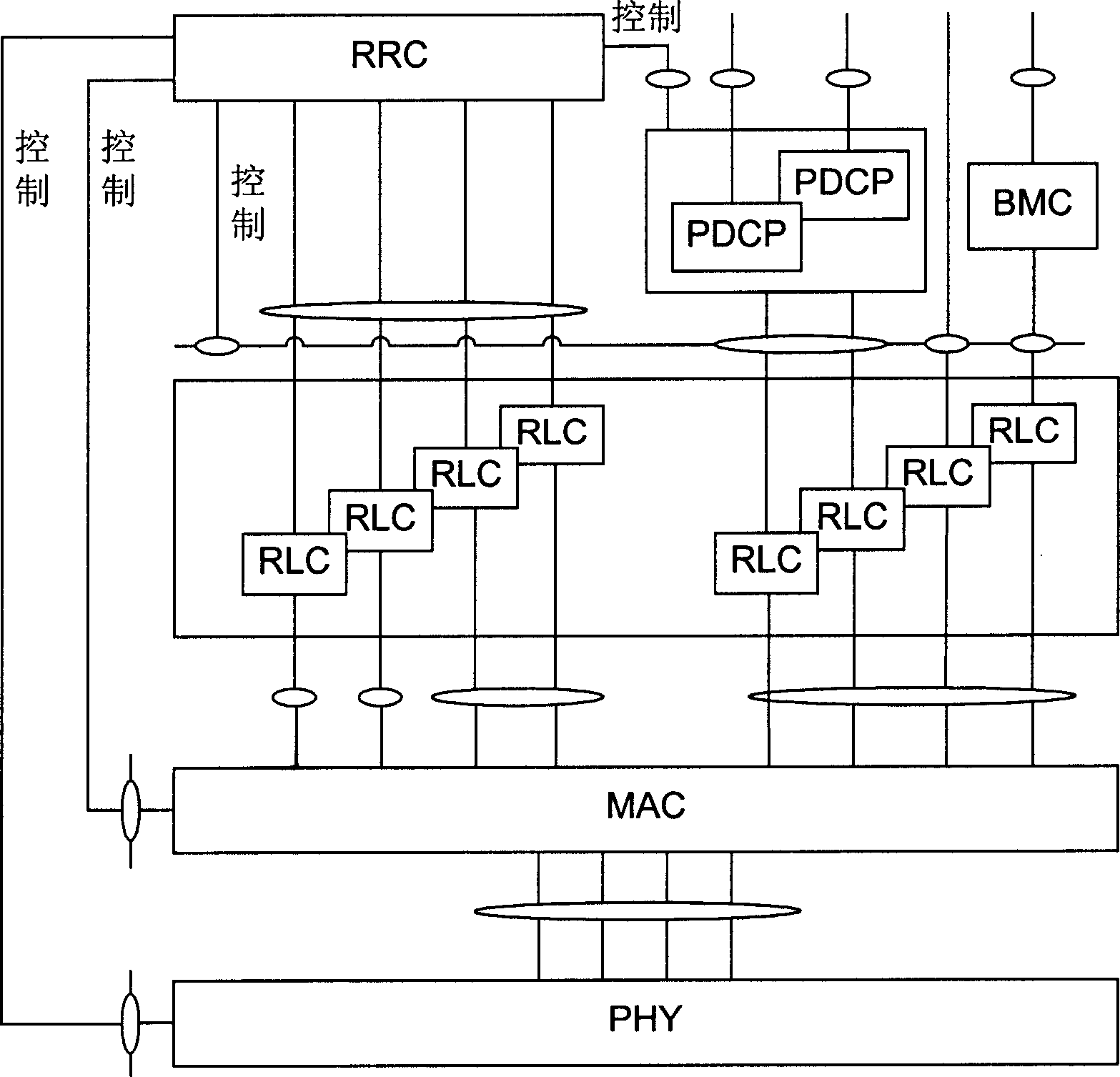
[0031] In communication systems implemented based on various standards, the data link layer of the wireless interface part provides data frame confirmation and / or retransmission mechanisms. Taking the WCDMA (WCDMA Wideband Code Division Multiple Access) system as an example, the structure of the wireless interface protocol between the UTRAN (UTMS Terrestrial Radio Access Network, UTMS Terrestrial Radio Access Network) and the user terminal is as follows: figure 1 shown. The wireless access interface protocol includes the physical layer (PHY), data link layer and network layer, and the data link layer includes MAC (Media Access Control) layer, RLC (Radio Link Control) layer, PDCP (Packet Data Convergence Protocol) Layer and BMC (Broadcast / Multicast Control) layer, network layer includes RRC (Radio Resource Control) layer.

[0032] Among them, the physical layer is connected to the data link layer through different service access points, and provides different transmission chan...


PUM


Abstract

This invention discloses a method for monitoring a receiving end of data receiving by a sending end including the following steps: the sending end receives the confirmed information for the received data sent by the receiving end and accumulates the SUMr received by the receiving end successfully or the SUMe in the monitored period to compute the error block rate for receiving data by the receiving end based on the SUMe / (SUMr+SUMe).

Description

technical field [0001] The invention relates to the field of communication, in particular to a method for a sending end to monitor data receiving conditions of a receiving end. Background technique [0002] In an existing communication system, when a user terminal establishes a call or other data connection with another user terminal or service content provider through the network side, each terminal and the network side need to perform synchronization control and power control. Synchronous control ensures that the two parties in communication can correctly receive the data sent by the other party, while power control ensures the quality of the signal received by the terminal (base station or user terminal), and can maximize the capacity of the system. That is to say, the transmit power control is to achieve the effect of keeping the transmit power at a lower level at the transmitting end as much as possible while enabling the receiving end to obtain sufficient signal qualit...

Claims


Application Information

Patent Timeline
Patent Type & Authority Applications(China)
IPC IPC(8): H04L1/16H04B7/005
Inventor 吴玉忠张劲林
Owner HUAWEI TECH CO LTD
Why Eureka
Try Eureka