Brake actuator

A brake device and brake technology, applied in the direction of manufacturing tools, other manufacturing equipment/tools, textiles and papermaking, etc., can solve the problem of 38 flatness of the braking surface (smoothness is easy to produce deviations, etc.)

Active Publication Date: 2010-09-22
TSUDAKOMA KOGYO KK
View PDF5 Cites 1 Cited by
  • Summary
  • Abstract
  • Description
  • Claims
  • Application Information

AI Technical Summary

Problems solved by technology

[0014] In this regard, if the width dimension of the brake disc 28 (especially the braking surface 38) is enlarged (that is, the area of ​​the braking surface 38 is widened), the plane of the braking surface 38 on the yarn 14 running side Degree (smoothness) becomes prone to deviation

Method used


Image

  • Brake actuator
  • Brake actuator
  • Brake actuator

Examples


Embodiment 1

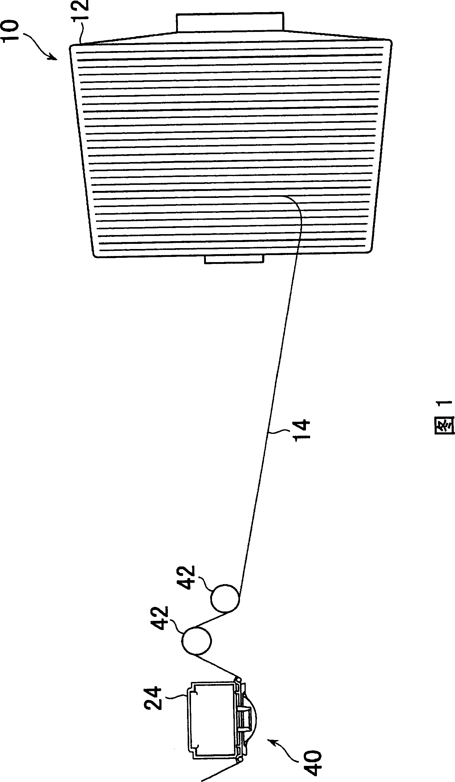
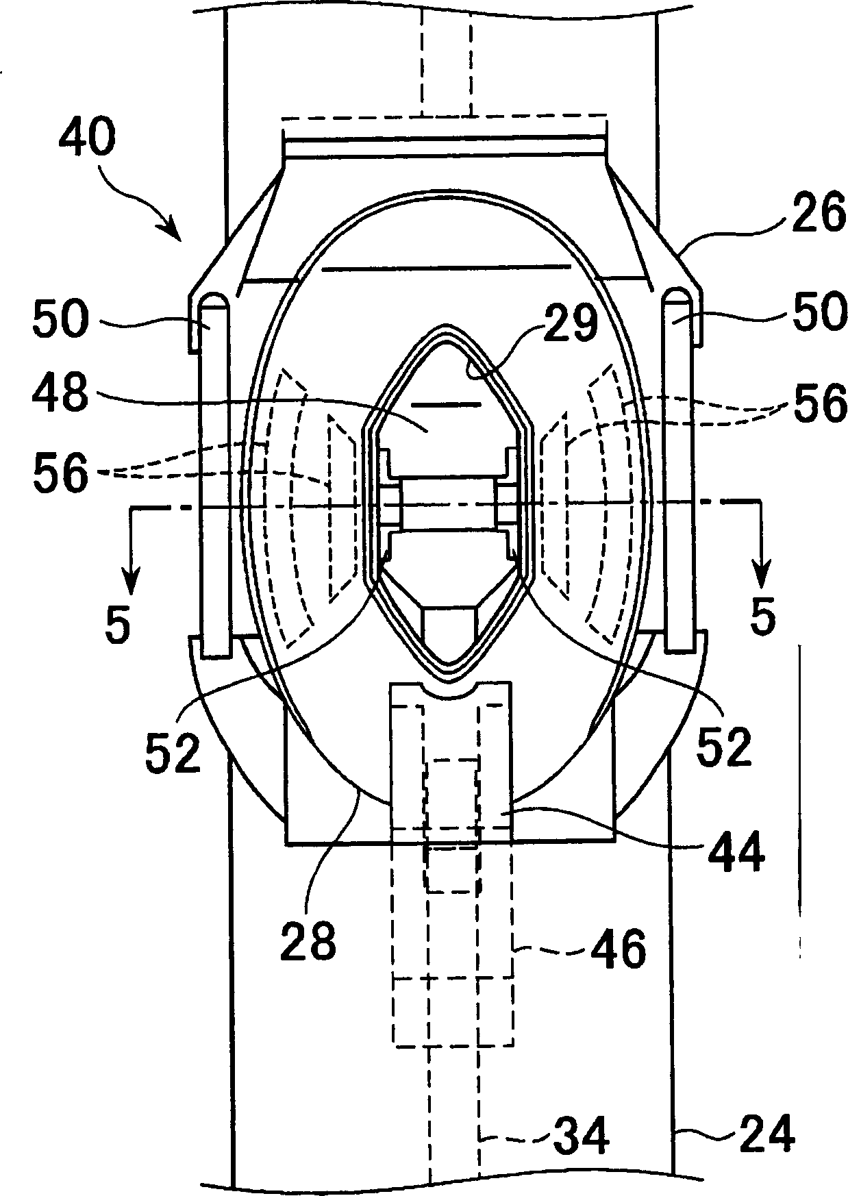
[0048] refer to Figure 2 to Figure 5 , braking device 40 with Figure 18 The shown existing brake device 22 is the same, including: a brake main body 26 installed on the combination rod 24; The brake plate 28 on the front side of 26.

[0049] The stopper plate 28 has a hole 29 in the center. The hole 29 has an elliptical shape in the illustrated example, but may be formed in an appropriate shape.

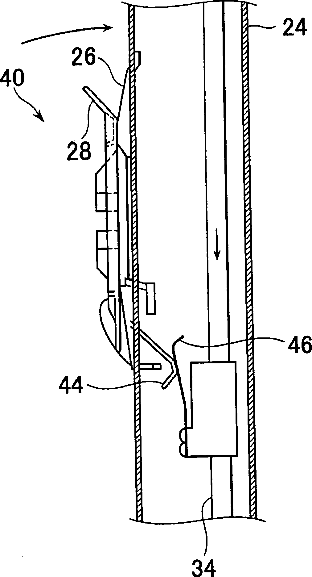
[0050] The lower end of the stopper plate 28 is pivotally connected to the lower end of the stopper body 26 , and the plate cam 44 is integrally formed at the lower end. The leaf spring 46 is attached to the rod 34 so as to be able to move up and down simultaneously with the rod 34 .

[0051] When the lever 34 descends, the plate cam 44 comes into contact with the plate spring 46 , and the plate spring 46 presses the stopper plate 28 toward one side. Thus, if image 3 The brake pads 28 are shown closed.

[0052] When the lever 34 rises, the plate cam 44 is released from the ...


PUM

PropertyMeasurementUnit
widthaaaaaaaaaa
heightaaaaaaaaaa

Abstract

The invention discloses a braking device, which comprises the following parts: braking bulk, braking piece and projecting part, wherein multiple projecting parts are formed on at least one braking bulk and braking piece, which extends along running direction of transverse-pierced yarn; the center of braking bulk and braking piece forms at least one on one side and multiple on the other side from upstream to downstream sides.

Description

technical field [0001] The invention relates to a brake device for applying a brake to a yarn drawn from a creel. Background technique [0002] like Figure 16 As shown, there is a textile machinery creel 10 (Patent Document 1). This creel 10 includes a plurality of bobbins 12 . The yarn 14 wound on these bobbins 12 is pulled out by the warper 16 , and wound around a warp beam (beam) 20 in a sheet form after passing through a guide roller 18 of the warper 16 . [0003] Patent Document 1 Japanese Patent Publication No. Sho 63-28932 [0004] Such a creel 10, such as Figure 17 As shown, a braking device 22 for applying a braking force to the yarn 14 pulled out from the bobbin 12 to adjust the tension of the yarn 14 is arranged on each yarn 14 . The braking device 22 is mounted on a combination rod 24 disposed on the creel 10 . [0005] As one of such braking devices 22, such as Figure 18 shown. This conventional braking device 22 includes: a brake main body 26 installe...

Claims


Application Information

Patent Timeline
Patent Type & Authority Patents(China)
IPC IPC(8): D02H13/22
Inventor 相木宪一郎小林良治下村努
Owner TSUDAKOMA KOGYO KK
Why Eureka
Try Eureka