Display device and method for producing same

A technology for display devices and manufacturing methods, applied in static indicators, optics, instruments, etc., can solve problems such as ACF applied pressure connection, achieve effective connection, suppress formation, and reduce contact resistance

Active Publication Date: 2006-11-01
JAPAN DISPLAY INC
View PDF1 Cites 5 Cited by
  • Summary
  • Abstract
  • Description
  • Claims
  • Application Information

AI Technical Summary

Problems solved by technology

[0008] Here, in the above-mentioned terminal part, since the planarizing film is relatively soft, there is a problem that it is not possible to sufficiently connect the ACF with pressure.

Method used


Image

  • Display device and method for producing same
  • Display device and method for producing same
  • Display device and method for producing same

Examples


Embodiment Construction

[0044] Embodiments of the present invention will be described below with reference to the accompanying drawings.

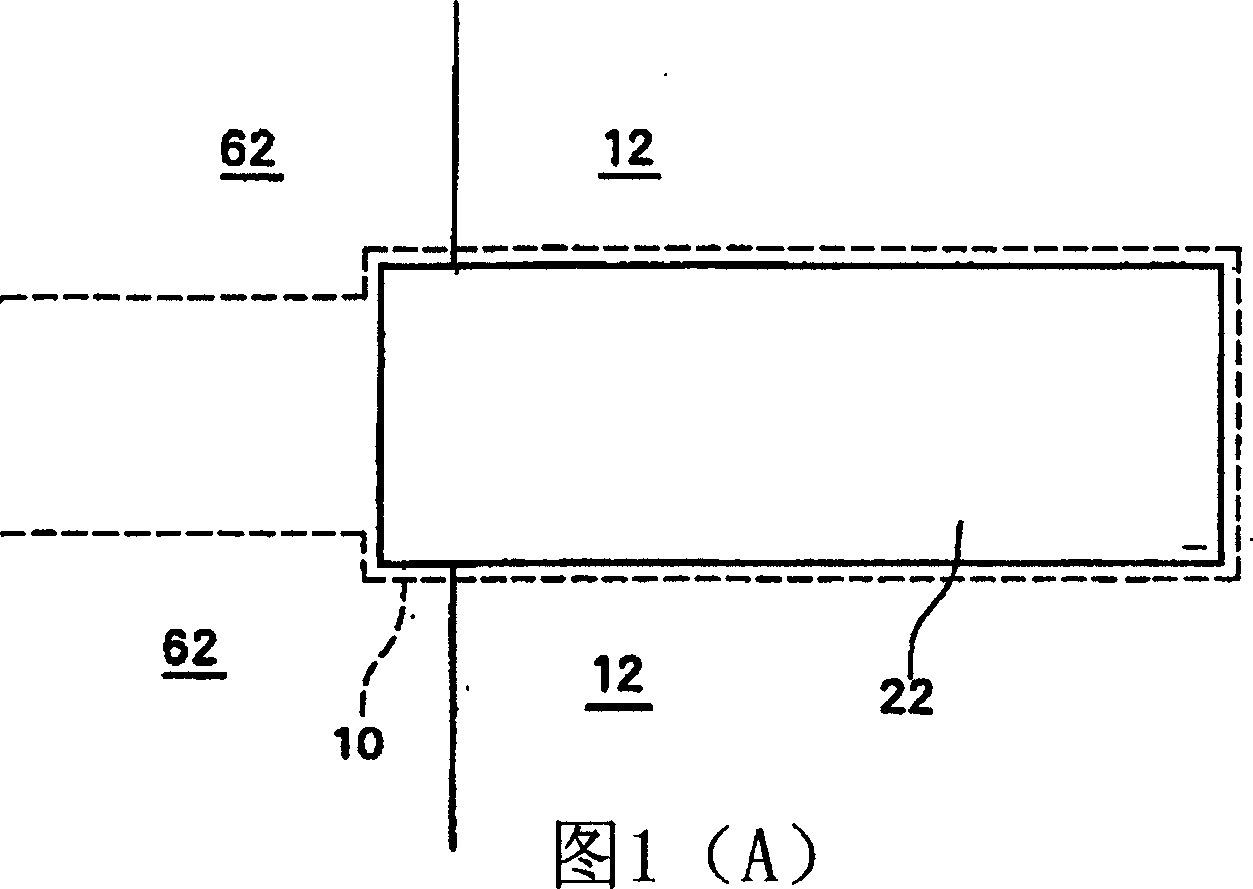
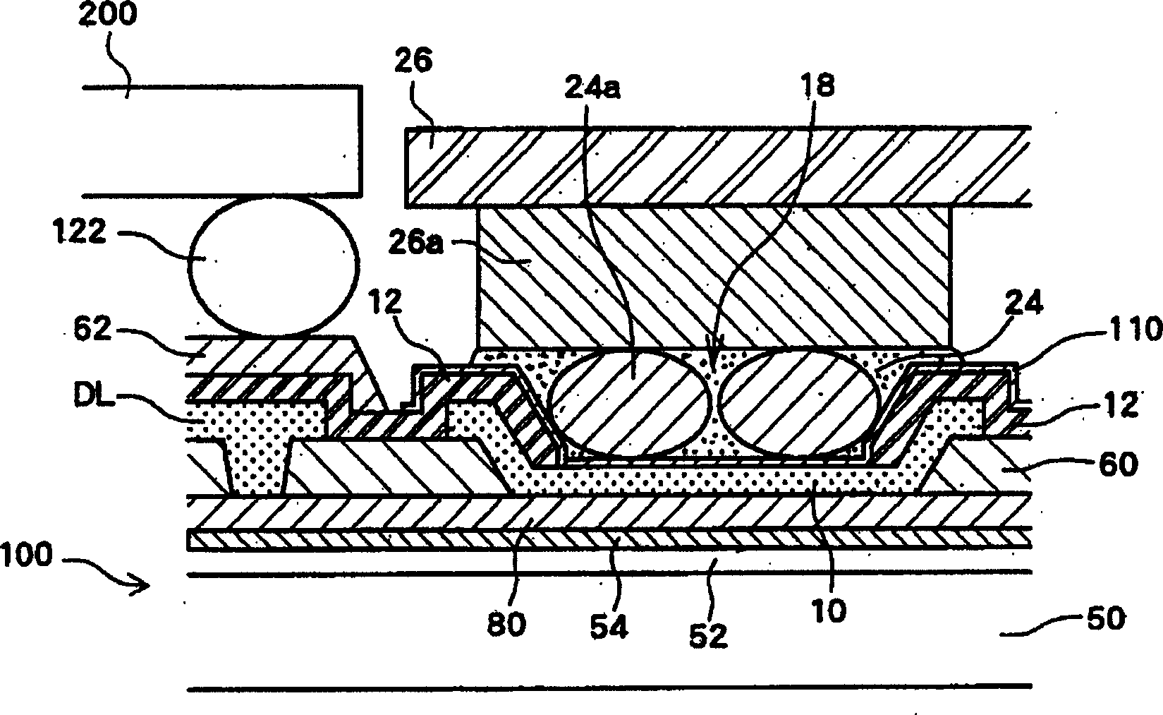
[0045] FIGS. 1(A) and 1(B) are structural diagrams showing the COG terminal portion according to this embodiment.

[0046] The data line DL is formed on the interlayer insulating film 60, extends to the peripheral portion, and is terminated right in front of the COG terminal portion. A contact hole is formed in the interlayer insulating film 60 at the end portion of the data line DL, and is connected to the molybdenum wiring 80 below. Furthermore, the molybdenum wiring 80 extends from the COG terminal portion, and the connecting wiring 10 is formed on the molybdenum wiring 80 . In addition, the molybdenum wiring 80 and the gate electrode (gate line) mentioned later are produced in the same process.

[0047] The protective film 12 is formed on the connection wiring 10 , the data line DL, and the interlayer insulating film 60 located between the connection wiring ...


PUM


Abstract

A portion of a protective layer located above a connection portion is removed to expose the connection portion which is formed of the same material as used for a data line DL in this removed portion. Then, a transparent conductive layer made of ITO is further formed on these films. The transparent conductive layer and a bump are then connected via an AFC.

Description

technical field [0001] The present invention relates to an active matrix display device having a COG (Chip on Glass) terminal portion for directly connecting other semiconductor integrated circuits to a peripheral portion, and a manufacturing method thereof. Background technique [0002] Conventionally, in display devices such as liquid crystal panels, active-matrix display devices in which display control thin-film transistors are arranged in each pixel have been widely used. [0003] In such a display device, a data signal (image signal) or the like from the outside is received into the panel, and the signal is supplied to each pixel. Therefore, vertical data lines and horizontal selection (gate) lines are provided, data signals are supplied to the data lines, and corresponding gate lines are used to select the pixels, and the supply of data signals to each pixel is controlled. Therefore, it is necessary to control the data supply to the data lines and the selection of th...

Claims


Application Information

Patent Timeline
Patent Type & Authority Applications(China)
IPC IPC(8): G02F1/133G02F1/1333G02F1/136G09G3/36H01L27/00
CPCG02F1/1345G02F1/13452G02F1/136
Inventor 小田信彦
Owner JAPAN DISPLAY INC
Why Eureka
Try Eureka