Piezoelectric membrane resonator and wave filter with same

一种压电薄膜、谐振器的技术,应用在压电器件/电致伸缩器件、压电/电致伸缩器件的制造/组装、用于压电器件或电致伸缩器件的材料选择等方向,能够解决谐振特性和滤波特性劣化、谐振特性和滤波特性改变、降低可靠性等问题

Active Publication Date: 2006-11-01
TAIYO YUDEN KK
View PDF6 Cites 7 Cited by
  • Summary
  • Abstract
  • Description
  • Claims
  • Application Information

AI Technical Summary

Problems solved by technology

[0008] However, there is a problem in Conventional Technology 1, Conventional Technology 2, and Conventional Technology 3 in that resonance characteristics and filter characteristics change with variations caused by manufacturing processes
In addition, there are other problems in Conventional Technology 4 and Conventional Technology 5 in that resonance characteristics and filter characteristics deteriorate
In addition, conventional technologies 1 to 5 all have the common problem of low reliability
Moreover, if the resonance characteristics and filter characteristics are further improved, the resonance characteristics and filter characteristics will be changed, and the reliability will be reduced

Method used


Image

  • Piezoelectric membrane resonator and wave filter with same
  • Piezoelectric membrane resonator and wave filter with same
  • Piezoelectric membrane resonator and wave filter with same

Examples


no. 1 example

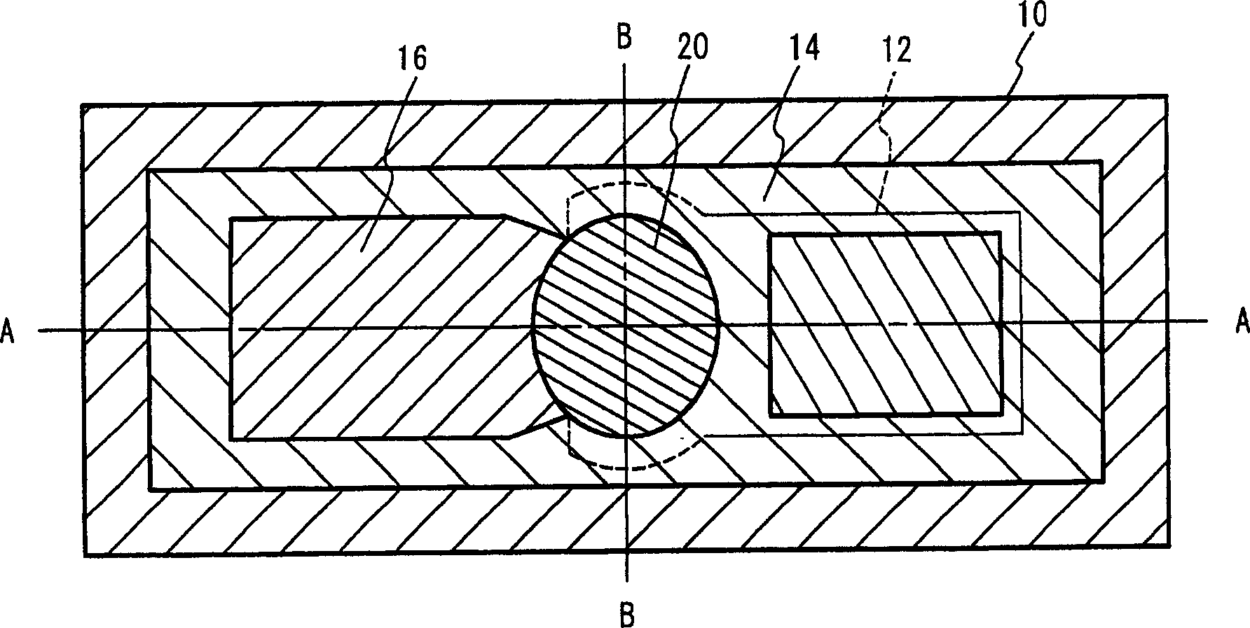
[0034] Figure 2A to Figure 2C is a view illustrating the structure of the piezoelectric thin film resonator according to the first embodiment of the present invention. Figure 2A is a top view of the piezoelectric thin film resonator according to the first embodiment of the present invention. Figure 2B is along Figure 2A A cross-sectional view taken along line A-A shown in . Figure 2C is along Figure 2A A cross-sectional view taken along line B-B shown in . The lower electrode 12 is placed on the silicon substrate 10 . The piezoelectric film 14 is placed on the lower electrode 12 . The upper electrode 16 is placed on the piezoelectric film 14 . The diaphragm region 22 corresponds to a region where the upper electrode 16 and the lower electrode 12 overlap each other so as to sandwich the piezoelectric thin film 14 . The piezoelectric film 14 placed on the lower electrode 12 is partially removed, and a hole for connection is formed. The void 18 having the same size ...

no. 2 example

[0052] Another example of a resonator will be explained in the second embodiment. The resonator employed in the second embodiment has an enlarged region in which a silicon oxide film serving as the center frequency adjustment film 20 is to be formed. Figure 8A is a top view of the resonator employed in the first embodiment, and the center frequency adjustment film 20 is not shown. Figure 8B shows the Figure 8A The center frequency in the illustrated resonator adjusts the area of ​​the membrane 20 . As shown in FIG. 8B , the center frequency adjustment film 20 is formed only in the diaphragm region 22 .

[0053] FIG. 8C shows a region in which the center frequency adjustment film 20a is formed according to the second embodiment. Center frequency adjustment film 20 a is formed in a region other than windows provided for joining upper electrode 16 and lower electrode 12 . That is, the center frequency adjustment film 20a is formed larger than the diaphragm region 22 to incl...


PUM


Abstract

A piezoelectric thin-film resonator includes a lower electrode provided on a substrate, a piezoelectric thin film provided on the lower electrode, and an upper electrode provided on the piezoelectric thin film. A membrane region is defined by a region where the upper electrode and the lower electrode overlap each other to sandwich the piezoelectric thin film therebetween and has an elliptical shape, and the lower electrode is also provided at an outer side of the membrane region in a region in which neither an extraction electrode of the upper electrode nor an extraction electrode of the lower electrode is provided.

Description

technical field [0001] The present invention generally relates to piezoelectric thin film resonators and filters, and more particularly, to piezoelectric thin film resonators and filters having the same in which mutually overlapping An upper electrode and a lower electrode sandwich a piezoelectric film therebetween. Background technique [0002] With the rapid expansion of high-frequency wireless devices represented by mobile phones, there is an increasing need for small-sized and light-weight high-frequency filters for use in the high-frequency band of 900 MHz to 5 GHz. Filters mainly including surface acoustic wave devices are used in the above fields. Today, however, attention is focused on piezoelectric thin film resonators and filters having them because the devices have excellent high-frequency characteristics, can be miniaturized, and can be fabricated onto a single substrate. [0003] Piezoelectric thin film resonators include, for example, film bulk acoustic reson...

Claims


Application Information

Patent Timeline
Patent Type & Authority Applications(China)
IPC IPC(8): H03H9/15H01L41/08H01L41/09H01L41/18H01L41/22H01L41/253H01L41/29H03H9/17H03H9/54
CPCH03H3/04H03H9/132H03H9/173H03H9/174H03H2003/0428H03H2003/0457H03H9/15
Inventor 横山刚西原时弘谷口真司坂下武堤润岩城匡郁上田政则
Owner TAIYO YUDEN KK
Why Eureka
Try Eureka