System and method for increasing concentration of sterilant in region

一种区域、净化系统的技术,应用在厕所用的卫生设备、消毒、建筑等方向,能够解决影响作用时间等问题

Active Publication Date: 2006-11-08
AMERICAN STERILIZER CO
View PDF0 Cites 4 Cited by
  • Summary
  • Abstract
  • Description
  • Claims
  • Application Information

AI Technical Summary

Problems solved by technology

However, use in large-scale isolation chambers, ie, 5,000 cubic feet or larger, may greatly affect duration of action

Method used


Image

  • System and method for increasing concentration of sterilant in region
  • System and method for increasing concentration of sterilant in region

Examples


Embodiment Construction

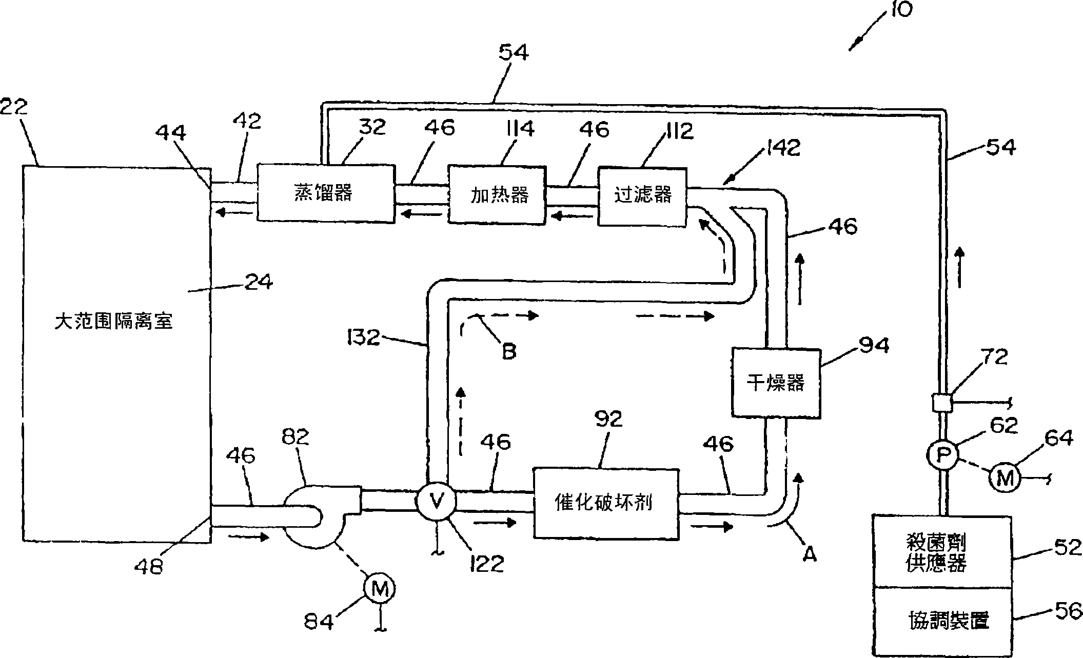
[0046] Referring to the accompanying drawings, the accompanying drawings shown therein are only used to illustrate the preferred embodiments of the above-mentioned invention, but are not limited to the above-mentioned embodiments for the same purpose, figure 1 A vapor hydrogen peroxide sterilization system 10 illustrating a preferred embodiment of the present invention is shown. System 10 includes an isolation chamber 22 that defines an interior sterilization or decontamination chamber or zone 24 . The objects to be processed will be placed inside the processing space or isolation chamber 22 . A retort (also referred to as a generator) 32 is connected to the sterilizing or decontaminating room or isolation room 22 of the zone 24 using a supply line 42 . Supply conduit 42 defines a vaporous hydrogen peroxide inlet 44 to a chamber or region 24 . The distiller 32 is connected to a liquid sterilant supply 52 via a feed line 54 . It is known that a balance device 56 is associate...


PUM


Abstract

A vapor decontamination system for decontaminating a defined region. The system is comprised of a chamber defining a region, and a generator for generating vaporized hydrogen peroxide from a solution of hydrogen peroxide and water. A closed loop circulating system is provided for supplying the vaporized hydrogen peroxide to the region. A destroyer within the closed loop circulating system breaks down the vaporized hydrogen peroxide. A bypass conduit is provided to bypass the destroyer. A controller causes vaporized hydrogen peroxide from the generator to bypass the destroyer during a predetermined phase of operation.

Description

technical field [0001] The invention is related to general sterilization and purification technology, especially a system with synthetic gas or steam bactericide in the sterilization or purification system. Background technique [0002] Bactericidal methods are widely used and are also used with a wide range of fungicides. When the term sterilization is used herein, it refers to the inactivation of biological contaminants, mainly on inanimate objects. The term decontamination refers to the inactivation of pathogenic organisms. [0003] Gas and vapor sterilization or decontamination systems rely on maintaining specific process parameters in order to achieve sterility goals or guaranteed decontamination standards. For hydrogen peroxide vapor sterilization or purification systems, these parameters include concentration, saturation, temperature, pressure and contact time of hydrogen peroxide vapor. By controlling these parameters, it is expected that the criteria for assuring...

Claims


Application Information

Patent Timeline
Patent Type & Authority Applications(China)
IPC IPC(8): A61L2/00A61LA61L2/20
CPCA61L2/208A61L2/24A61L2202/14A61L2202/25A61L2202/122A61L2202/11
Inventor 艾伦 L·希尔麦克 A·巴西客
Owner AMERICAN STERILIZER CO
Why Eureka
Try Eureka