

Heat exchanger and artificial lung
A heat exchanger, hollow technology, applied in the direction of suction equipment, drug equipment, other medical equipment, etc., can solve the problem of hydrogen peroxide concentration increase, and achieve the effect of preventing concentration increase
- Summary
- Abstract
- Description
- Claims
- Application Information
AI Technical Summary
Problems solved by technology
Method used
Image

Examples
no. 1 approach
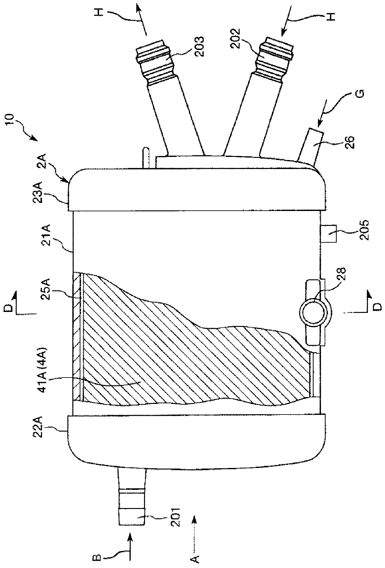
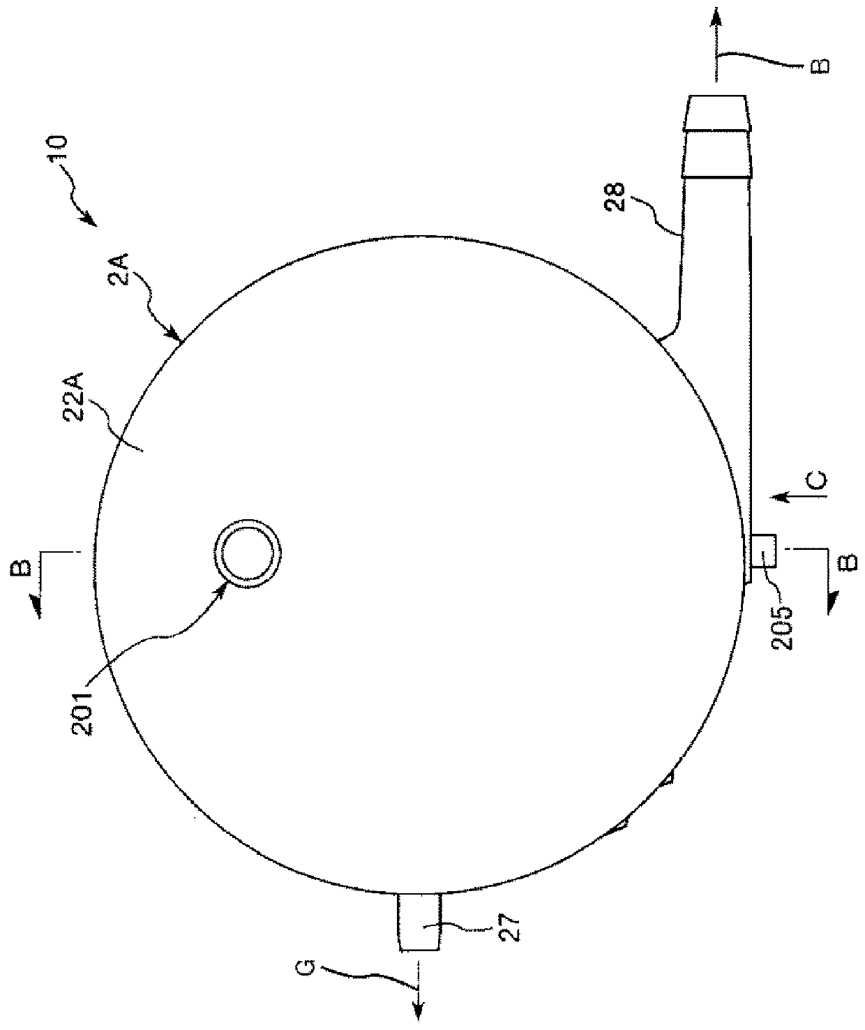
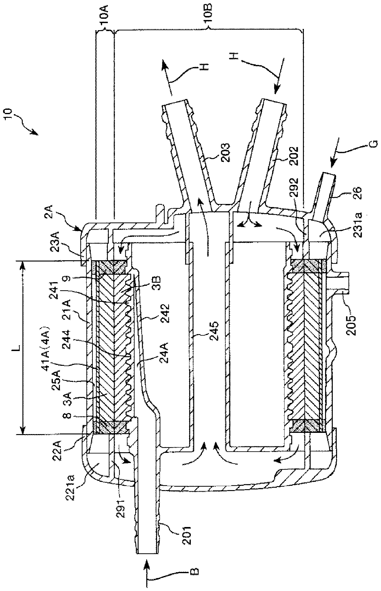
[0046] figure 1 It is a plan view of the artificial lung provided with the heat exchanger (first embodiment) of the present invention. figure 2 For viewing from the direction of arrow A figure 1 A diagram of the artificial lung is shown. image 3 for figure 2 B-B line sectional view in. Figure 4 for from figure 2 The figure viewed from the direction of the arrow C in the figure. Figure 5 for figure 1 D-D line sectional view in . Figure 6 for Figure 5 E-E line sectional view in. Figure 7 Made to show figure 1 The figure ((a) is a perspective view, (b) is a developed view) of the process of the hollow-fiber membrane layer which the artificial lung has shown is shown. Figure 8 Made to show figure 1 The figure ((a) is a perspective view, (b) is a developed view) of the process of the hollow-fiber membrane layer which the artificial lung has shown is shown. Figure 9 for figure 1 A cross-sectional view of a hollow fiber membrane included in the hollow fiber me...
no. 2 approach
[0104] Figure 11 It is a plan view showing the hollow fiber membrane sheet before being formed into the hollow fiber membrane layer included in the heat exchanger (second embodiment) of the present invention. Figure 12 To show the Figure 11 The perspective view of the hollow fiber membrane layer formed by folding the hollow fiber membrane sheet shown.
[0105] Hereinafter, a second embodiment of the heat exchanger according to the present invention will be described with reference to this figure, but the description will focus on the differences from the above-mentioned embodiment, and the description of the same items will be omitted.
[0106] This embodiment is the same as the above-mentioned first embodiment except that the structure of the hollow fiber membrane layer is different.
[0107] The hollow fiber membrane layer 3C in the artificial lung 10 in this embodiment consists of Figure 11 The illustrated hollow fiber membrane sheet 300 is constructed.
[0108] The...
no. 3 approach
[0112] Figure 13 It is a perspective view showing the hollow fiber membrane layer included in the heat exchanger (third embodiment) of the present invention.
[0113] Hereinafter, a third embodiment of the heat exchanger according to the present invention will be described with reference to this figure, but the description will focus on the differences from the above-mentioned embodiment, and the description of the same items will be omitted.
[0114] This embodiment is the same as the above-mentioned first embodiment except that the structure of the hollow fiber membrane layer is different.
[0115] Such as Figure 13 As shown, the hollow fiber membrane layer 3D is the Figure 11 The illustrated hollow fiber membrane sheet 300 is wound into a roll and formed into a cylinder a plurality of times.
[0116] Also in this embodiment described above, the same effects as those of the first embodiment and the second embodiment described above can be exhibited.
[0117] As mentio...
PUM
| Property | Measurement | Unit |
|---|---|---|
| thermal conductivity | aaaaa | aaaaa |
| length | aaaaa | aaaaa |
| thickness | aaaaa | aaaaa |
Abstract
Description
Claims
Application Information