Touching type induction regulator for vacuum cleaner

An induction regulator and vacuum cleaner technology, which is applied in the installation of electrical equipment, electrical components, control systems, etc., can solve the problems of increased investment, limited selection of knobs or sliders, and reduced generalization of the speed control circuit of vacuum cleaners. Comfort, productivity, and generalization effects

Inactive Publication Date: 2006-11-15
LG ELECTRONICS (TIANJIN) APPLIANCES CO LTD
View PDF0 Cites 7 Cited by
  • Summary
  • Abstract
  • Description
  • Claims
  • Application Information

AI Technical Summary

Problems solved by technology

At the same time, due to the restriction of the stroke of the potentiometer, the selection of the position of the knob or slider on the vacuum cleaner is also limited, and it is often necessary to re-develop a new speed regulating circuit with the same function and only the position of the potentiometer changes.
In this way, the degree of generalization of the speed regulating circuit of the vacuum cleaner will be reduced, which is not conducive to the convenience of customers and increases the investment.

Method used


Image

  • Touching type induction regulator for vacuum cleaner
  • Touching type induction regulator for vacuum cleaner
  • Touching type induction regulator for vacuum cleaner

Examples


Embodiment Construction

[0022] The specific embodiment of the present invention will be further described in conjunction with the accompanying drawings.

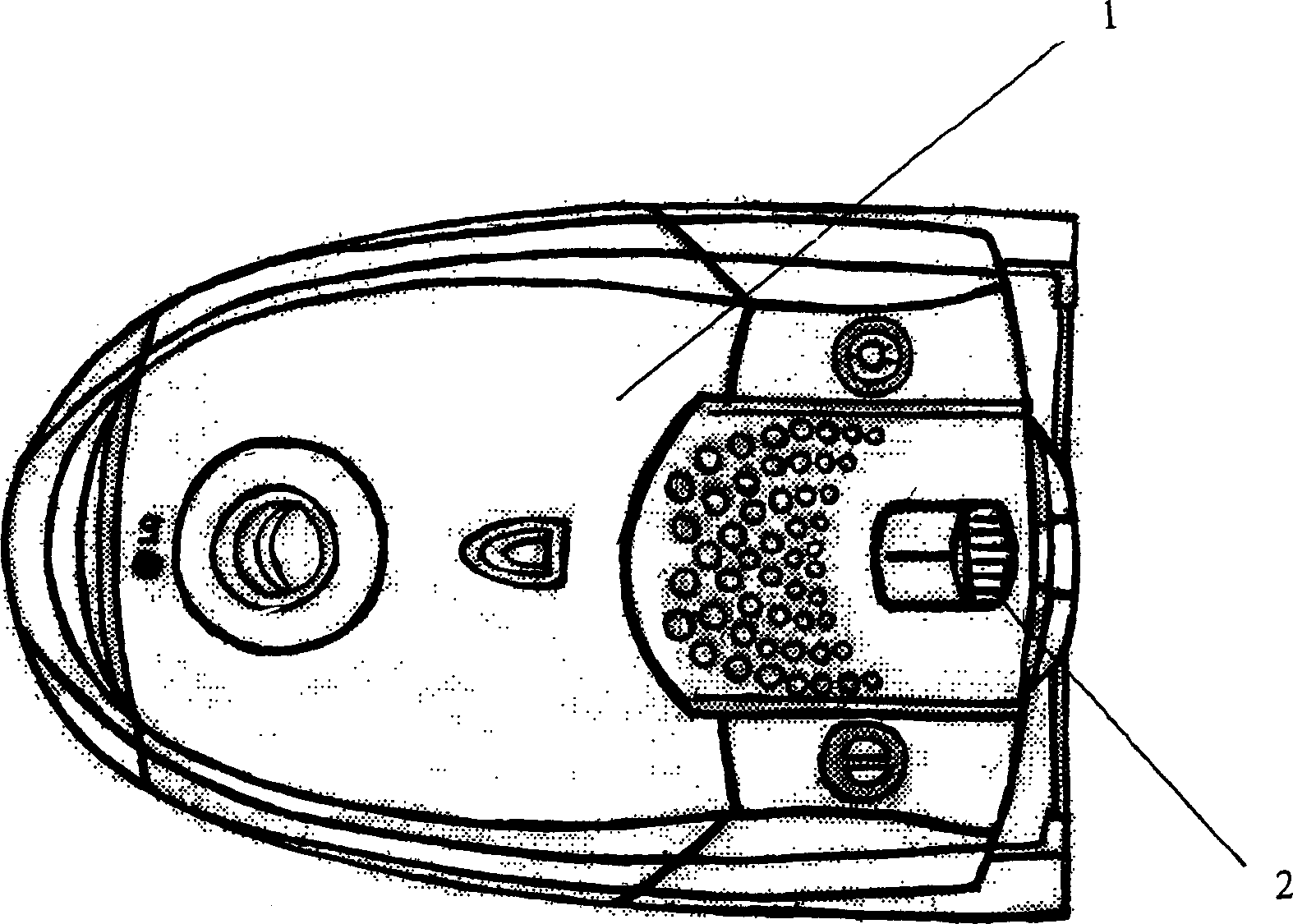
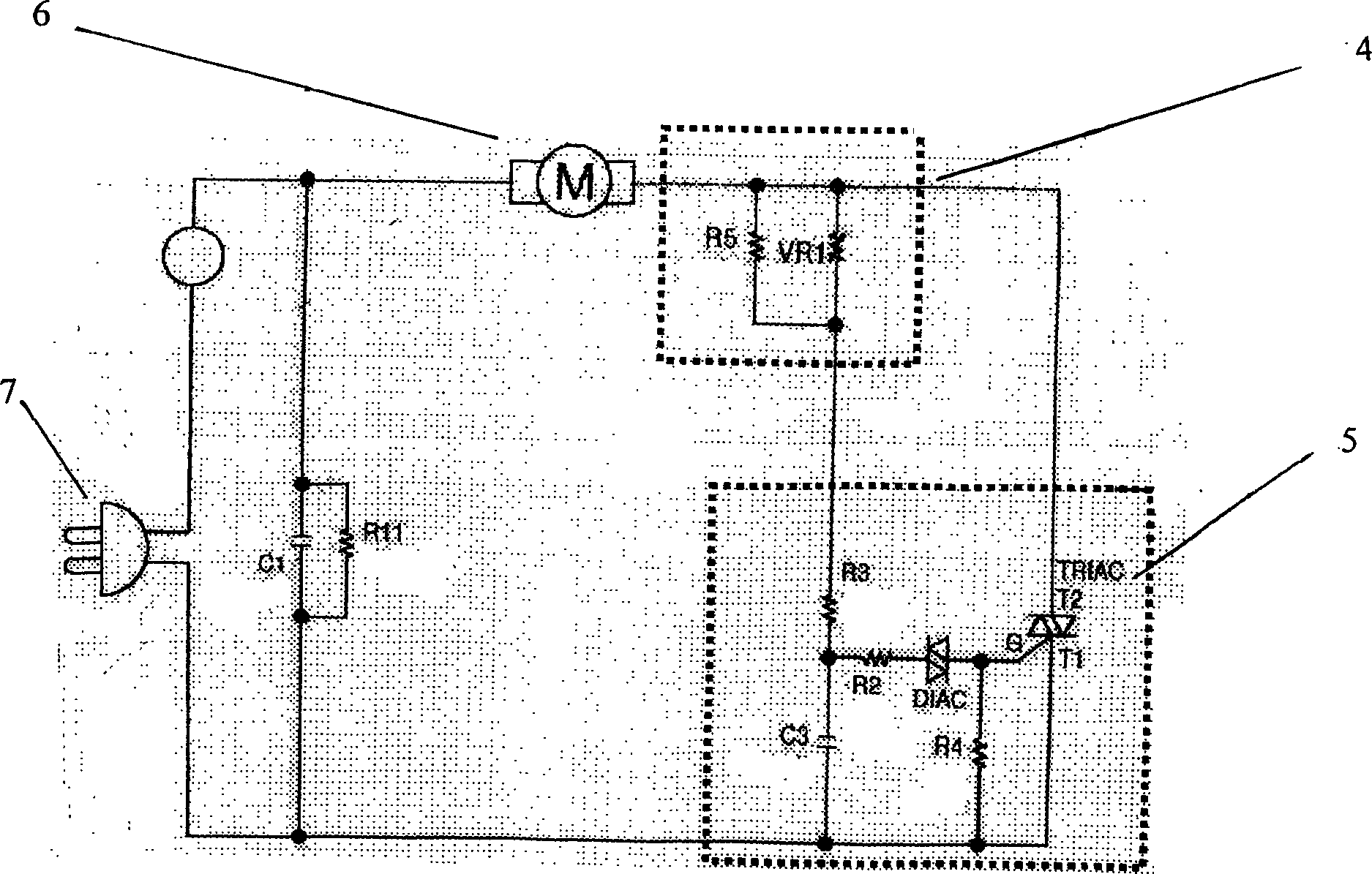
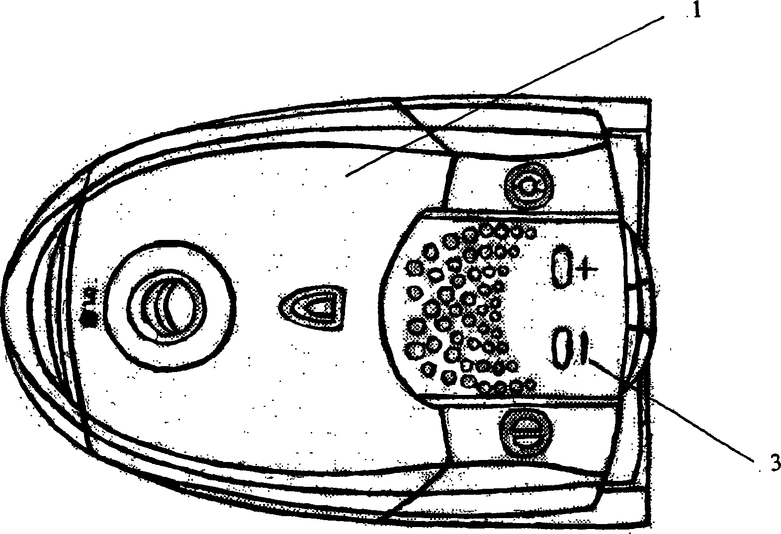
[0023] image 3 It is the exterior view of the vacuum cleaner housing involved in the present invention, Figure 4 It is a block diagram of the vacuum cleaner speed regulating circuit involved in the present invention. As shown in the figure, the vacuum cleaner touch sensor regulator of the present invention includes an operation button disposed on the vacuum cleaner housing and a speed regulating circuit disposed inside the vacuum cleaner. The operation button is designed as a button, which is composed of two touch pads 3 that respectively play the role of speeding up and decelerating, and the touch pads 3 are respectively connected with the two terminals of the touch input end of the speed regulating circuit. The speed regulation circuit includes input buffer, phase locked loop, state and phase angle memory, digital comparator, drive circuit, t...


PUM


Abstract

A touch induction type speed regulator of cleaner is composed of an operation knob arranged on the casing of cleaner and consisting of an acceleration piece and a deceleration piece and a speed regulating circuit connected to said two pieces for regulating the speed of motor and consisting of input buffer, phase lock ring, state and phase angle memory, digital comparator, driver and SCR.

Description

technical field [0001] The invention relates to a vacuum cleaner, in particular to a suction rate regulating device of the vacuum cleaner. Background technique [0002] Vacuum cleaners are a kind of cleaning and hygiene household appliances, which are used to remove dust from floors, carpets, walls, furniture and various gaps. Generally speaking, the components of the vacuum cleaner mainly include the body, the suction head and the suction pipe, etc. The suction device mainly formed by the motor and the fan is arranged in the body. Communicate with the body. After the power is turned on, the motor drives the impeller of the fan to rotate at a high speed, exhausting the air in the vacuum cleaner, forming an instantaneous vacuum in the vacuum cleaner, and forming a relatively high negative pressure difference with the outside atmosphere. Under the action of this negative pressure difference, the garbage and dust near the suction port of the suction head are sucked into the b...

Claims


Application Information

Patent Timeline
Patent Type & Authority Applications(China)
IPC IPC(8): A47L9/28H02P23/00
Inventor 金涛
Owner LG ELECTRONICS (TIANJIN) APPLIANCES CO LTD
Why Eureka
Try Eureka