
High-performance universal multi-channel radar system

A radar system and a generalized technology, applied in the field of radar systems, can solve problems such as high requirements for acquisition synchronization, waste of design and development resources, and insufficient flexibility, and achieve low requirements for acquisition bandwidth and synchronization accuracy, reduce acquisition bandwidth and synchronization Accuracy requirements, the effect of reducing quality problems

Active Publication Date: 2019-04-19
SHANGHAI RADIO EQUIP RES INST
View PDF6 Cites 8 Cited by
  • Summary
  • Abstract
  • Description
  • Claims
  • Application Information

AI Technical Summary

Problems solved by technology

Under the framework of the traditional multi-channel radar system, there are usually common and contradictory components in the same component. This unreasonableness makes different application requirements correspond to different multi-channel radar hardware, and it is difficult to solve the problem of low design and development efficiency and lack of versatility. Strong and insufficient flexibility
[0004] Although the existing independently developed multi-channel radar signal acquisition devices can effectively improve the development efficiency and improve the versatility and flexibility of the multi-channel radar system, there are still problems with high signal acquisition bandwidth, high acquisition synchronization requirements, and inadequate system architecture division. , leading to the waste of design and development resources
[0005] In the prior art, in the invention patent with application number 201611009563.2 "A multi-channel radar signal acquisition device based on digital channelization", and in the invention patent with application number 201110383300.9 "Design of multi-channel broadband electronic signal synchronous acquisition system In " and Implementation Method", the scheme of front-end array + multi-channel signal acquisition device is adopted. Although it can improve the versatility of the entire multi-channel radar system to a certain extent, it still cannot overcome the inherent problem of independently developing the multi-channel radar signal acquisition device solution. shortcoming
[0006] In the invention patent "A Modular, Building Block Digital Array Radar System" with application number 201610864367.7, a new multi-channel radar system architecture is proposed, trying to solve the problem of generalization of radar under different requirements. However, the architecture Only considering the difference in the form of the antenna array, it still greatly limits the scope of application of this generalized multi-channel radar system
[0007] In the invention patent "pulse fully coherent generalized experimental radar" with application number 201510357316.0, a structure of antenna + front end + microwave source + signal processor is adopted, which can realize the generalization of single-channel radar system, but the structure Can not meet the needs of multi-channel radar
[0008] Based on the above, the present invention proposes a high-performance generalized multi-channel radar system. Aiming at the problems of low design and development efficiency, poor versatility and insufficient flexibility in the development of multi-channel radar systems, starting from the source design, the commonality is summarized part, highlight the contradictory part, and combine key technical means to solve the shortcomings and limitations of the existing technology

Method used


Image

  • High-performance universal multi-channel radar system
  • High-performance universal multi-channel radar system
  • High-performance universal multi-channel radar system

Examples


Embodiment Construction

[0026] The following combination Figure 1 to Figure 5 , the technical content, structural features, achieved goals and effects of the present invention will be described in detail through preferred embodiments.

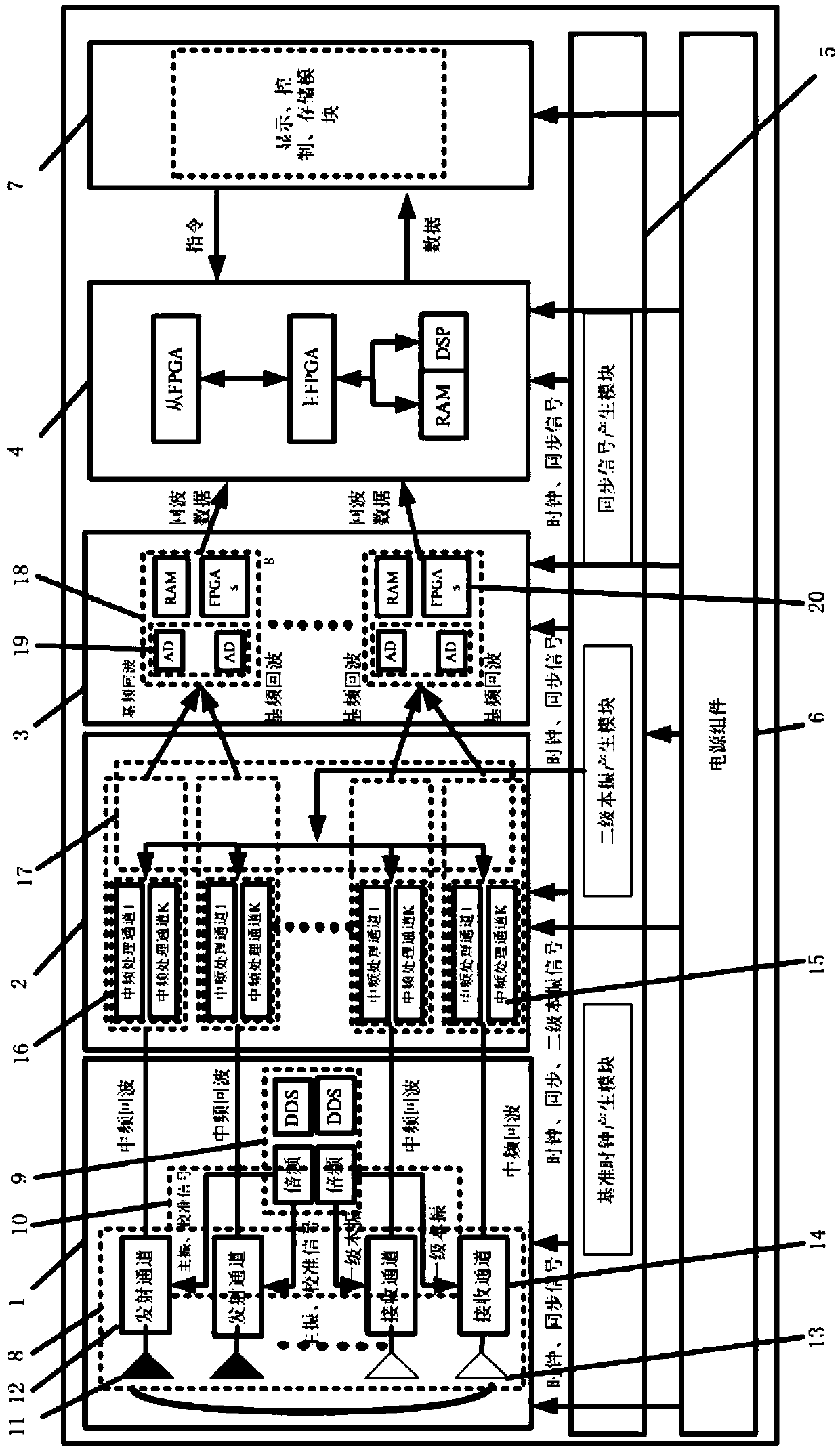
[0027] Such as figure 1 As shown, the high-performance generalized multi-channel radar system provided by the present invention includes: a high-frequency front-end component 1, an intermediate frequency processing component 2, a data acquisition component 3, an integrated signal processing component 4 connected in sequence, and the above-mentioned components respectively Connected microwave source assembly 5; wherein, the high-frequency front-end assembly 1 adopts a specialized high-frequency front-end assembly for millimeter-wave short-range imaging.

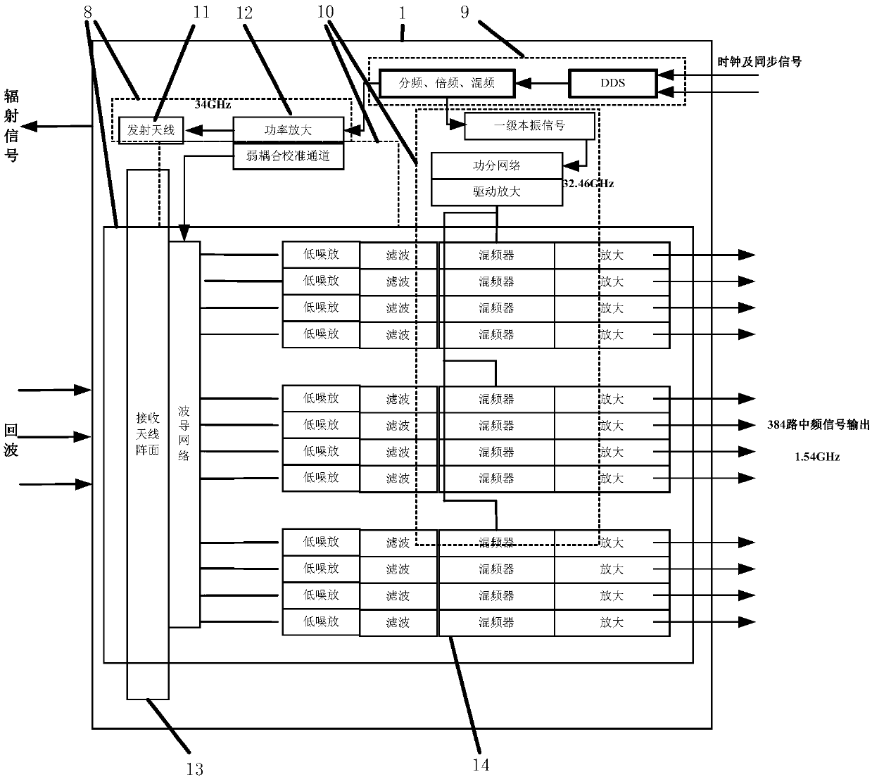
[0028] In different application situations, the high-frequency front-end component 1 needs to be specially designed. Such as figure 1 and 2 As shown, the millimeter-wave short-range imaging high-frequency front-e...


PUM


Abstract

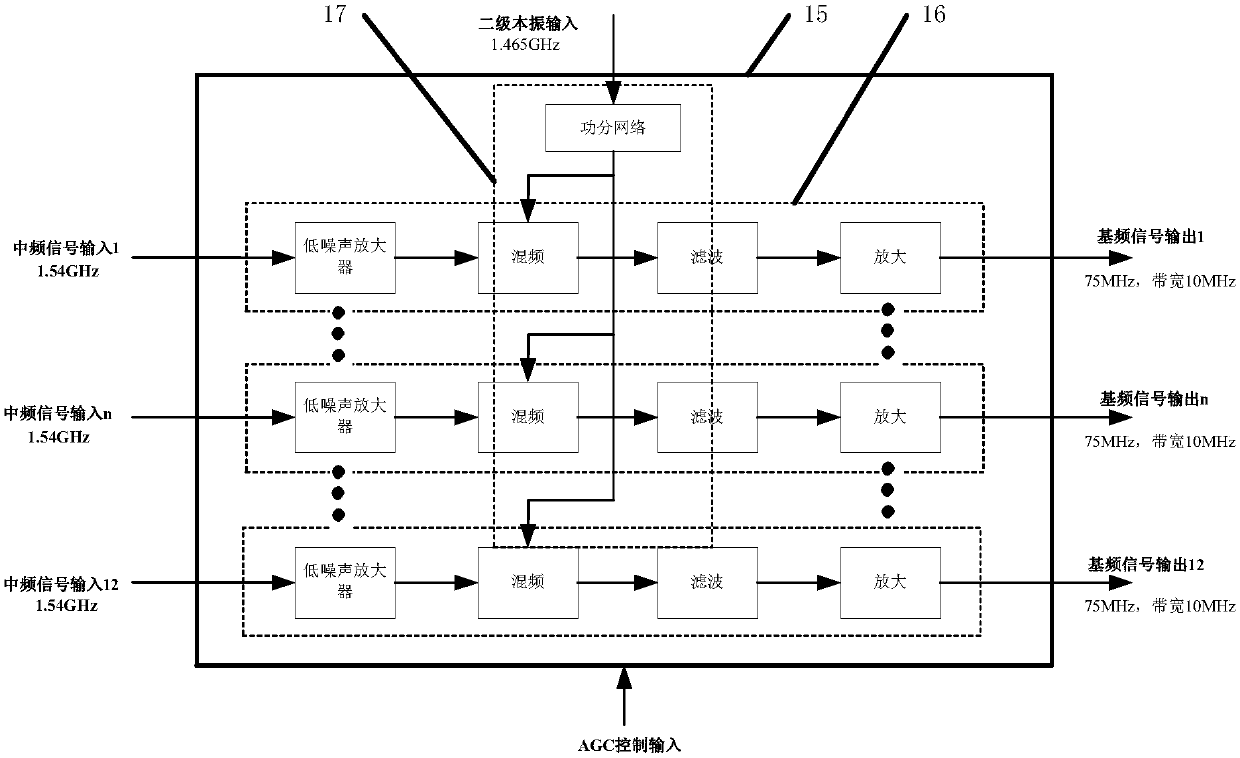
A high-performance universal multi-channel radar system comprises a millimeter wave short-range imaging high-frequency front-end assembly, an intermediate frequency processing assembly, a data acquisition assembly, a comprehensive signal processing assembly and a microwave source assembly. The high-frequency front-end assembly comprises a radio frequency and local oscillator signal generation module, a signal distribution and calibration network module, an antenna and a radio frequency channel array module, and realizes generation of radio frequency and primary local oscillator signals, and reception, amplification, filtering and primary down-conversion of echo signals. The intermediate frequency processing assembly realizes amplification, filtering and secondary down-conversion of echo signals. The data acquisition assembly is used for realizing echo signal acquisition and signal preprocessing. Real-time imaging of echo data is achieved through the comprehensive signal processing assembly. The microwave source assembly realizes generation of a clock reference signal, a synchronous signal and a secondary local oscillator signal. Resource waste caused by repeated design and development under same requirement or similar requirement is avoided, the design efficiency is effectively improved, and universality and flexibility are enhanced.

Description

technical field [0001] The invention relates to a radar system, specifically a multi-channel radar system with high performance and general characteristics, and belongs to the technical field of overall scheme design and signal processing of the multi-channel radar system. Background technique [0002] In the complex electromagnetic environment, the application scenarios of modern radars are becoming more and more complex, making it difficult for single-channel radars to meet the growing application requirements. In application scenarios such as clutter suppression, stealth target detection and positioning, and moving target detection insurmountable difficulty. Compared with traditional single-channel radar, multi-channel radar benefits from the introduction of multi-channel digital beamforming technology, which not only can replace single-channel radar in traditional application scenarios to achieve target detection, but also can achieve target detection in scenarios where ...

Claims


Application Information

Patent Timeline
Patent Type & Authority Applications(China)
IPC IPC(8): G01S7/40G01S7/41G01S7/28G01S7/35
CPCG01S7/28G01S7/35G01S7/4021G01S7/41
Inventor 唐琳刘斌黄勇王凤娇孟宏峰陈曦吕良卿
Owner SHANGHAI RADIO EQUIP RES INST
Learn More