Electric portable fertilizer-and-seeder

A fertilizer applicator and portable technology, applied in the field of electric portable seeding fertilizer applicators, can solve the problems of single function, unreliable work, poor terrain adaptability, etc., achieve a high degree of generalization, reliable operation, and improve market competitiveness Effect

Active Publication Date: 2016-11-23
KUNMING UNIV OF SCI & TECH
View PDF7 Cites 7 Cited by
  • Summary
  • Abstract
  • Description
  • Claims
  • Application Information

AI Technical Summary

Problems solved by technology

[0003] There are many types of existing portable seeders, but most of them need to be planted and fertilized by pushing the top support plate by hand, such as the "portable seeder" disclosed in the utility model patent CN201084900Y. Higher and labor-saving, but to varying degrees, there are problems such as single function, unreliable work, and poor adaptability to terrain, so it cannot be widely used

Method used


Image

  • Electric portable fertilizer-and-seeder
  • Electric portable fertilizer-and-seeder
  • Electric portable fertilizer-and-seeder

Examples


Embodiment 1

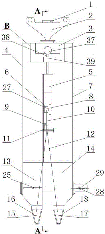
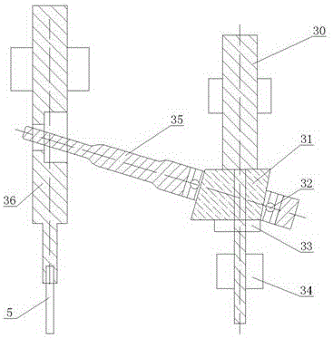
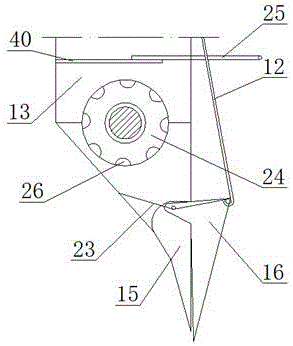
[0026] Embodiment 1: as Figure 1-6 As shown, an electric portable seeding and fertilizing machine includes a switch 1, a handle 2, a battery 3, a seed box 4, a drive rod 5, a gear 6, a fertilizer box 7, a flywheel 8, a roller 9, a duckbill connecting rod 10, Cam 11, triangular pull rod 12, seed collecting box 13, fertilizer collecting box 14, sowing fixed duckbill 15, sowing movable duckbill 16, fertilizing fixed duckbill 17, fertilizing movable duckbill 18, sector gear 19, connecting shaft 20, connecting shaft Rod 21, shift fork 22, return spring 23, seed wheel 24, seed number adjustment control plate 25, seed collection pit 26, ratchet 27, motor 37, coupling 38, electric transmission mechanism 39, strapping plate 40, The electric transmission mechanism 39 includes a rotating main shaft 30, an eccentric block 31, a bearing I 32, a fixed block 33, a bearing II 34, a swing rod 35, and a guide rod 36;

[0027]The switch 1 is fixedly embedded in the handle 2, the storage batter...

Embodiment 2

[0029] Embodiment 2: as Figure 1-6 As shown, an electric portable seeding and fertilizing machine includes a switch 1, a handle 2, a battery 3, a seed box 4, a drive rod 5, a gear 6, a fertilizer box 7, a flywheel 8, a roller 9, a duckbill connecting rod 10, Cam 11, triangular pull rod 12, seed collecting box 13, fertilizer collecting box 14, sowing fixed duckbill 15, sowing movable duckbill 16, fertilizing fixed duckbill 17, fertilizing movable duckbill 18, sector gear 19, connecting shaft 20, connecting shaft Rod 21, shift fork 22, return spring 23, seed wheel 24, seed number adjustment control plate 25, seed collection pit 26, ratchet 27, motor 37, coupling 38, electric transmission mechanism 39, strapping plate 40, The electric transmission mechanism 39 includes a rotating main shaft 30, an eccentric block 31, a bearing I 32, a fixed block 33, a bearing II 34, a swing rod 35, and a guide rod 36;

[0030] The switch 1 is fixedly embedded in the handle 2, the storage batte...


PUM


Abstract

The invention relates to an electric portable fertilizer-and-seeder and belongs to the field of agricultural machinery. The electric portable fertilizer-and-seeder comprises a switch, a grip, a storage battery, a seed case, a drive rod, a gear, a manure box, a flywheel, a rolling wheel, a duckbill connecting rod, a cam, a triangular pull rod, a seed collection box, a manure collection box, a fixed seeding duckbill, a movable seeding duckbill, a fixed fertilizing duckbill, a movable fertilizing duckbill, a sector gear, a connecting shaft, a connecting rod, a shifting fork, a reset spring, a planting wheel, a grain number adjusting control board, a seed collection pit, a ratchet, a motor, a coupler, an electric transmission mechanism and a butt strap; the electric transmission mechanism comprises a rotatable spindle, an eccentric block, a bearing I, a fixing block, a bearing II, an oscillating rod and a guide rod. By the arrangement, working efficiency in agriculture mechanization production is greatly improved, land fertilization can be performed according to cultivation of different crops and different seasons, and the utilization rate of fertilizer can be increased.

Description

technical field [0001] The invention relates to an electric portable seeding and fertilizing machine, which belongs to the field of agricultural machinery. Background technique [0002] In view of the particularity of hilly and mountainous areas, although sowing has been effectively reformed and sowing machinery has been popularized, but for more complex mountainous areas, sowing machinery is still in short supply. Terrain, compared with traditional human planting machinery, is more labor-saving and time-saving, and it is also a pollution-free and environmentally friendly product. [0003] There are many types of existing portable seeders, but most of them need to be planted and fertilized by pushing the top support plate by hand, such as the "portable seeder" disclosed in the utility model patent CN201084900Y. Higher and labor-saving, but there are problems such as single function, unreliable work, and poor terrain adaptability to varying degrees, so they cannot be widely ...

Claims


Application Information

Patent Timeline
Patent Type & Authority Applications(China)
IPC IPC(8): A01C7/06A01C19/02
CPCA01C7/06A01C19/02Y02P60/14
Inventor 朱惠斌成习军白丽珍朱凯张健伟曹科高李宏刚王宇航邵亚兴
Owner KUNMING UNIV OF SCI & TECH
Why Eureka
Try Eureka