Heat-pipe cooling type grinding roller

A cooling type, heat pipe technology, applied in grain processing, etc., can solve the problems of dangerous maintenance, inconvenience, safety of processed materials such as leaking, leaking, leakage, etc., and achieve the effect of good cooling effect, convenient use and simple structure

Inactive Publication Date: 2006-11-15
康建文
View PDF1 Cites 13 Cited by
  • Summary
  • Abstract
  • Description
  • Claims
  • Application Information

AI Technical Summary

Problems solved by technology

It overcomes the need for a special water circulation system for water-cooled grinding rollers, and the danger to the sa

Method used


Image

  • Heat-pipe cooling type grinding roller

Examples


Example Embodiment

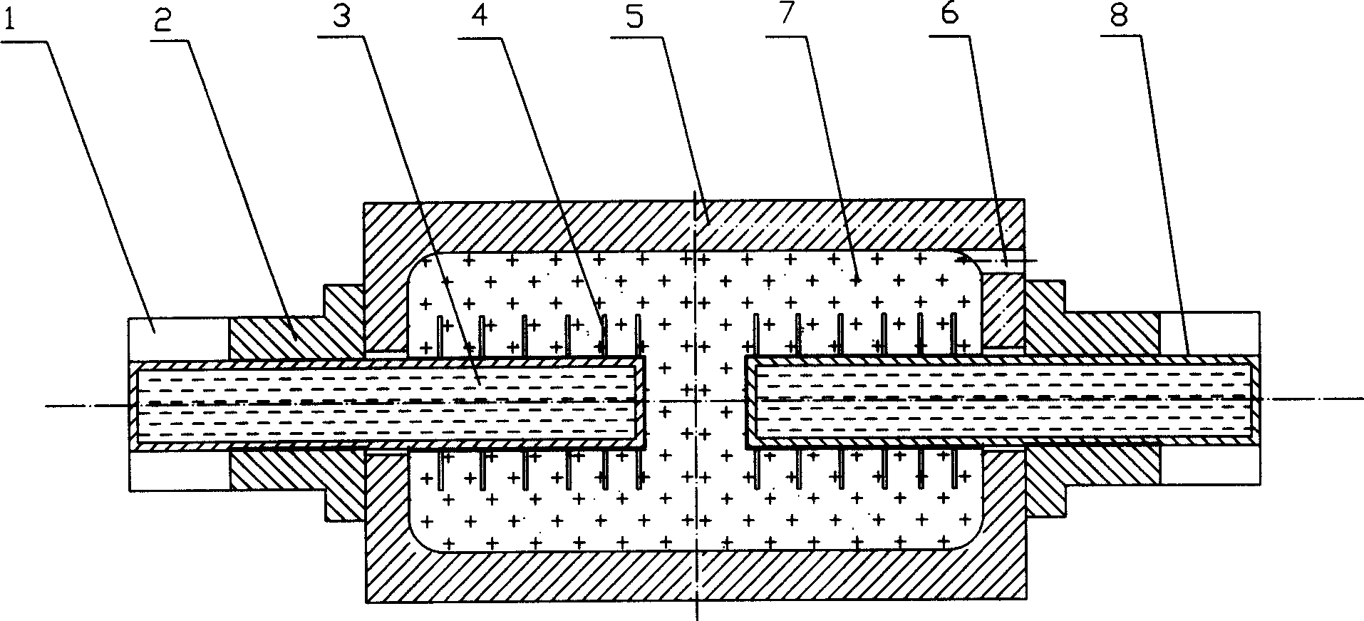
[0019] like figure 1 As shown, a heat pipe cooling grinding roller includes: a hollow roller body 5, a hollow shaft head 2 connected at both ends of the roller body, and communicates with the inner cavity of the hollow roller body 5, and the inner hole of the hollow shaft head 2 is in line with the horizontal The excircle of rotary heat pipe 8 fits closely, and the heated end of heat pipe stretches into the inner chamber of roller body, and the radiating end of heat pipe stretches out the axle head outside, and the inner cavity of hollow roller body is annotated with heat transfer medium 7.

[0020] There are two horizontally rotating heat pipes 8, the outer circles of which are closely matched with the inner holes of the two hollow shaft heads respectively.

[0021] In order to improve the heat absorption effect, the heat receiving end of the heat pipe is provided with heat absorption fins 4 ; in order to improve the heat dissipation effect, the heat dissipation end of the he...


PUM


Abstract

A heat tube cooled grinding roller is composed of a hollow roller body, two hollow axle heads connected to both ends of said roller body, a heat conducting medium filled in said hollow roller body, and two heat tubes with one heat reception end inserted in the internal cavity of said roller body and having heat absorbing fins and one heat radiating end extended out of said axle head and having heat radiating fins.

Description

technical field [0001] The present invention relates to crushing or crushing using a roller mill, in particular to the improvement of the roller cooling device of the roller mill. Background technique [0002] The roller mill is the main equipment for processing grain, oil, food and chemical products (raw materials), and the grinding roller is the main working part of the roller mill. The grinding roller is a hollow metal cylinder with solid shaft heads connected at both ends, which can rotate around its axis. Its working process is: feeding materials (grain, oil, chemical products and chemical raw materials) between a pair of horizontal grinding rollers rotating in opposite directions at differential speeds, extruding, peeling and scraping, so as to achieve the effect of crushing and grinding materials. During the grinding process of the material, not only the internal extrusion and friction will generate heat, but also the relatively pushing friction between the material ...

Claims


Application Information

Patent Timeline
IPC IPC(8): B02C4/30B02C4/44
Inventor 康建文
Owner 康建文
Why Eureka
Try Eureka