Motor controlling method

A control method and motor technology, applied in the direction of AC motor control, motor, control drive, etc., can solve the problems of motor stall, motor burnout, slow response speed, etc., and achieve the effects of smooth start, prevention of overshoot, and fast acceleration

Inactive Publication Date: 2006-11-15
BYD CO LTD
View PDF0 Cites 22 Cited by
  • Summary
  • Abstract
  • Description
  • Claims
  • Application Information

AI Technical Summary

Problems solved by technology

In the speed loop feedback control, the throttle depth corresponds to the given speed, and then the speed controls i q To control the torque, so its response speed is slow
At the same time, when the electric vehicle is going uphill and othe

Method used


Image

  • Motor controlling method
  • Motor controlling method
  • Motor controlling method

Examples


Embodiment Construction

[0024] The present invention will be described in further detail below through specific embodiments and in conjunction with the accompanying drawings.

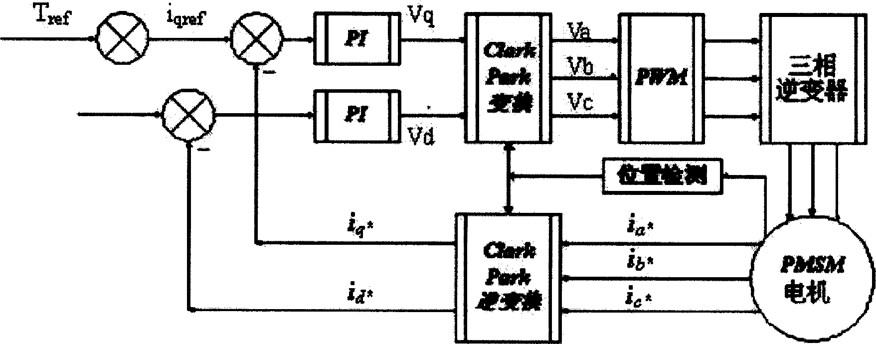
[0025] Such as figure 2 As shown, it is a schematic diagram of the motor current loop control system of the present invention. The control strategy involved in the present invention includes the following steps: detecting the gear position signal, the protection signal, the depth of the brake and the throttle, and the expected value of the motor current when performing PWM wave control of the motor Establish a corresponding relationship, and output the given values ​​of Id and Iq according to these data, that is, the target current; the current three-phase current i of the motor a* , i b* , i c* Calculate the actual current value i of the motor through park transformation and clark transformation q* , i d* ;Take the difference between the target current and the actual current as the input of the current loop, and output t...


PUM


Abstract

A motor control method with high dynamic response speed and high control precision features that the current loop control instead of speed loop control is used, in which the optimized PI control method is used, the depth of throttle is directly relative to the current iq for dynamically detecting the current value, and the difference between the target current and actual current is used as the input of current loop.

Description

technical field [0001] The invention relates to a motor control method, in particular to a motor control method for an electric vehicle. Background technique [0002] Motor control technology, the purpose of which is to control a continuously rotating motor using a rotating magnetic field. The requirements for motor control are very high, not only requiring the motor to work stably in various complex environments, but also requiring the physical quantities such as the motor's speed, rotation angle, and torque to be accurately controlled. [0003] The traditional control method adopts speed loop control, such as figure 1 shown. In the speed loop feedback control, the throttle depth corresponds to the given speed, and then the speed controls i q To control the torque, so its response speed is slow. At the same time, when the electric vehicle is going uphill and other road conditions are not good, the resistance is relatively large, and the motor is prone to stalling, the s...

Claims


Application Information

Patent Timeline
IPC IPC(8): B60L9/18B60L15/20H02P27/06
CPCY02T10/64Y02T10/72
Inventor 廖勇周旭光马先红齐阿喜杨广明谢飞张金涛
Owner BYD CO LTD
Why Eureka
Try Eureka