Cylindrical permanent magnetic system

A permanent magnet magnetic system, cylindrical technology, applied in the field of magnetic system, can solve the problems of increased cost of manufacturing magnets, unreachable air gap magnetic field, magnetic damage of permanent magnets, etc., and achieves high effective utilization rate and air gap magnetic density. High, strong anti-demagnetization effect

Inactive Publication Date: 2010-12-22
INST OF ELECTRICAL ENG CHINESE ACAD OF SCI
View PDF1 Cites 2 Cited by
  • Summary
  • Abstract
  • Description
  • Claims
  • Application Information

AI Technical Summary

Problems solved by technology

Theoretically, as long as the radial thickness and axial length of the permanent magnet ring are increased, the magnetic potential of the magnetic circuit can be increased, thereby increasing the air gap magnetic density. As the length increases, the volume and weight of the magnet also increase rapidly, which will cause a rapid increase in the cost of manufacturing the magnet; more importantly, when the air gap magnetic field continues to increase and is greater than the coercive force of the permanent magnet material, the magnetization direction The part of the permanent magnet ring close to the air gap in the opposite direction to the air gap magnetic field will inevitably be demagnetized, and the demagnetization phenomenon will irreversibly damage the magnetism of the permanent magnet, so that the air gap magnetic field cannot achieve the expected shape; in addition , the strong magnetic field in the same direction as the permanent magnet magnetization will cause the saturation phenomenon of the permanent magnet material, which will cause the operating point of the permanent magnet material to be in the first quadrant of its hysteresis loop instead of the second quadrant of normal operation, these Many technical difficulties in analysis and design make it difficult for this magnetic circuit to achieve a strong magnetic field

Method used


Image

  • Cylindrical permanent magnetic system
  • Cylindrical permanent magnetic system
  • Cylindrical permanent magnetic system

Examples


Embodiment Construction

[0017] The present invention will be further described below in conjunction with specific embodiments and accompanying drawings.

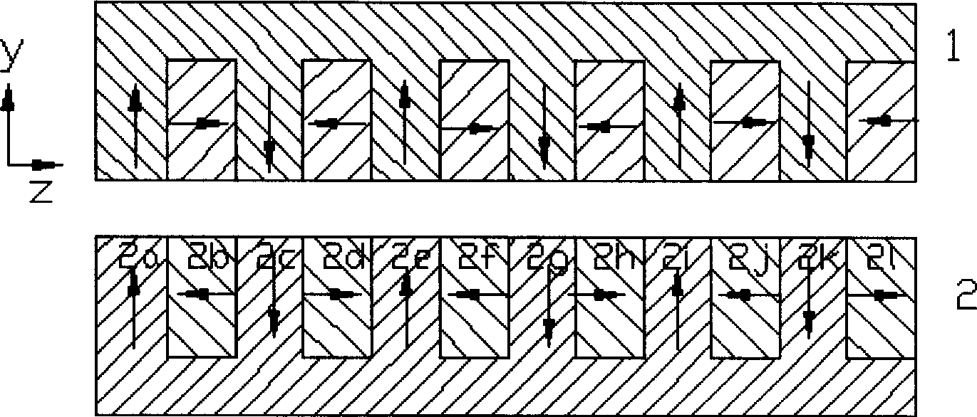
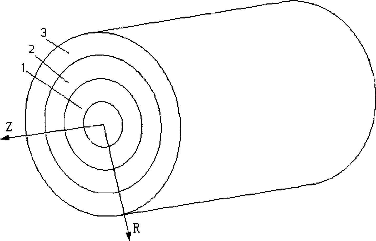
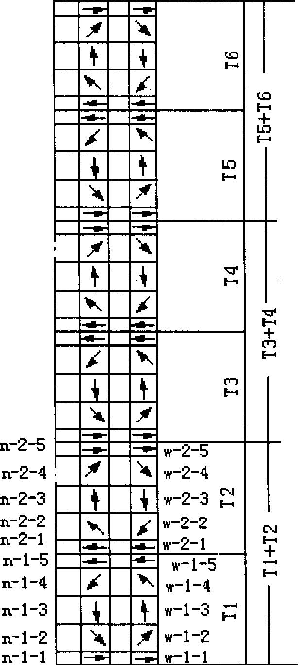
[0018] figure 2 It is a structural schematic diagram of a specific embodiment of the present invention. It consists of a periodic inner annular permanent magnet array 1, an annular air gap 2 and a periodic outer annular permanent magnet array 3 coaxially facing each other. The inner annular permanent magnet array 1 and the outer annular permanent magnet array 3 are axially aligned, and are composed of several NdFeB magnetic rings with a radial thickness of 50mm in the axial direction without spacing, and the geometric structure and magnetization direction are axisymmetric. and periodic. The inner annular permanent magnet array 1 adopts an external magnetic circuit structure, and the working air gap is the outer annular space of the inner annular permanent magnet array 1; the outer annular permanent magnet array 3 adopts an inner magnetic magneti...


PUM


Abstract

The invention discloses a cylinder-typed permanent magnetic system, which is composed of axial direction leveling and periodical inner ring-shaped permanent array and outer ring-shaped permanent array at the same shaft. The sine waveshape periodical magnetic field is formed on random axial cross section of ring-shaped gap between inner and outer ring-shaped permanent magnetic arrays, which is composed of several equal radial thickness neodymium ferroboron magnetic ring axial gapless periodical superpositions, whose geometrical structure and magnetic direction possess axial symmetry and periodicity. The invention reduces gap magnetic resistance and axial component of gap magnetic density, which improves spatial distribution pattern of gap magnetic density and utility rate.

Description

technical field [0001] The invention relates to a magnetic system of a cylindrical permanent magnet linear motor, in particular to a cylindrical permanent magnet magnetic system capable of generating a sinusoidal waveform periodic magnetic field. technical background [0002] Many devices require a periodic magnetic field with a sinusoidal waveform. US Patent US006057656A discloses a combined permanent magnet array, which generates a sinusoidal periodic magnetic field in the air gap formed by two oppositely arranged permanent magnet arrays, which can be used in the straight section of an electron accelerator. like figure 1 As shown, the combined permanent magnet arrays 1 and 2 are arranged in opposite directions. Each combined permanent magnet array is composed of a base magnetic block and several pole magnetic blocks. There are teeth and grooves on the base magnetic block, and the slots correspond to the pole magnetic blocks. , that is, the pole magnetic block is embedded...

Claims


Application Information

Patent Timeline
Patent Type & Authority Patents(China)
IPC IPC(8): H02K41/02H02K1/17
Inventor 赵凌志彭燕沙次文李然宋述军许玉玉
Owner INST OF ELECTRICAL ENG CHINESE ACAD OF SCI
Why Eureka
Try Eureka