Movable welding rod constant temperature material supply box

A feeding box, mobile technology, applied in the direction of welding equipment, auxiliary welding equipment, welding/cutting auxiliary equipment, etc., can solve the problems of easy moisture return, large power consumption, impractical secondary waste, etc.

Inactive Publication Date: 2006-11-29
CHENGXI SHIPYARD
View PDF0 Cites 4 Cited by
  • Summary
  • Abstract
  • Description
  • Claims
  • Application Information

AI Technical Summary

Problems solved by technology

Everyone is trying to find ways to better preserve welding rods. Larger companies have special welding rod drying rooms, welding rod insulation boxes and insulation cylinders. The power consumption is large,

Method used


Image

  • Movable welding rod constant temperature material supply box
  • Movable welding rod constant temperature material supply box
  • Movable welding rod constant temperature material supply box

Examples


Embodiment Construction

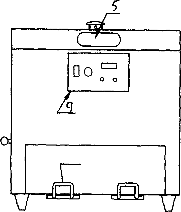
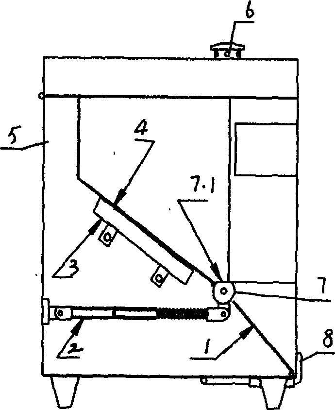
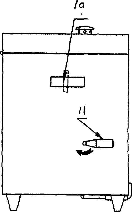
[0012] see figure 1 , 2 , 3, the present invention mobile electrode constant temperature supply box, mainly by material box 5, heat dissipation punching slant plate 4, electric heater 3, blanking shaft 7, blanking handle 11, guide slant plate 1, electrode bracket 8 , Reactor 2 and control panel 9. The heat dissipation punching slant plate 4 is arranged obliquely forward in the material box 5, the electric heater 3 is arranged on the back side of the heat dissipation punching slant plate 4, and the unloading shaft 7 is connected between the left and right side walls of the material box 5. The shaft 7 is placed on the front side of the lower edge of the heat-dissipating punching slant plate 4, and the connection between the unloading shaft 7 and the lower edge of the heat-dissipating punching slant plate 4 forms a plane 7.1, and the guide slant plate 1 is arranged obliquely forward in front of the unloading shaft 7 side, the welding rod bracket 8 is placed on the front and low...


PUM


Abstract

A movable constant-temp welding electrode supplying case is composed of casing body, perforated slope plate for heat dissipation, electric heater, discharging axle and handle, slope guide plate, welding electrode holder, reactive device and control panel.

Description

Technical field: [0001] The invention relates to an electrode, in particular to a mobile electrode constant temperature feeding box. It is mainly used for on-site cold work welding in shipbuilding and repairing enterprises. It belongs to the technical field of drying equipment. Background technique: [0002] People in the industry know that it takes a period of time for welding rods to be used from production to transportation, but after a long period of storage, the welding rods will be affected by humidity and the coating will be more likely to be damp, which will affect the quality of the welding rods and increase the difficulty of welding . Therefore, the welding rod insulation tube is usually used for on-site welding, and it is connected to the output end of the welding machine to heat it to make it reused. Everyone is trying to find ways to better preserve welding rods. Larger companies have special welding rod drying rooms, welding rod insulation boxes, and insulat...

Claims


Application Information

Patent Timeline
IPC IPC(8): B23K37/00
Inventor 吕德义
Owner CHENGXI SHIPYARD
Why Eureka
Try Eureka