Electromagnet for controlling shuttle box of weft machine

A shuttle box and electromagnet technology, which is applied in the field of electromagnets, can solve the problems of inaccurate positioning of the shuttle box, insufficient suction force, and increase of magnetic flux, etc., achieves obvious effects of magnetic flux gain, solves insufficient suction force, and increases magnetic flux.

Inactive Publication Date: 2006-11-29
冯加林
View PDF0 Cites 3 Cited by
  • Summary
  • Abstract
  • Description
  • Claims
  • Application Information

AI Technical Summary

Problems solved by technology

The cross-sectional area of ​​this electromagnet is limited by the above-mentioned structure, and its cross-section cannot be expanded according to the original cross-sectional shape structure to achieve the required magnetic flux value, so the suction force is insufficient.
When the lever is turned to push the tab to move, it often does not move down in place or cannot be disengaged from the tab in time, so that the shuttle box cannot be positioned accurately on the shuttle bar, thereby affecting the knitting quality
This problem has not been well resolved
Because, limited by the installation position, the method of enlarging the original cross-sectional area by a certain proportion, such as increasing the radius of the armature and the side length of the square yoke shell to increase the cross-sectional area and thereby increase the magnetic flux, becomes impossible to implement

Method used


Image

  • Electromagnet for controlling shuttle box of weft machine
  • Electromagnet for controlling shuttle box of weft machine
  • Electromagnet for controlling shuttle box of weft machine

Examples


Embodiment Construction

[0015] The present invention will be further described below in conjunction with the accompanying drawings and specific embodiments.

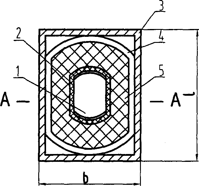
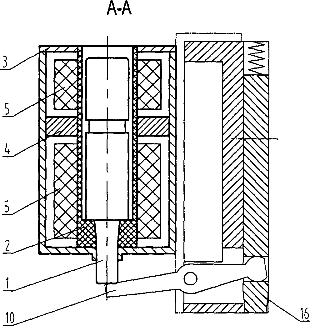
[0016] A specific embodiment of the device of the present invention see figure 1 , figure 2 . The cross section of the armature housing 3 is rectangular, with a side width b=25mm and the other side width l=32mm. The cross section of the armature 1 is a drum shape, and the cross sections of the magnetic steel 4, the skeleton 2 and the coil 5 are similar drum shapes. The skeleton 2 is plugged on the outside of the armature 1, and the magnetic steel 4 is plugged on the skeleton 2. The armature 1, the magnetic steel 4, the skeleton 2 and the coils wound on it form a magnetic core, and the magnetic core is fixed on the armature housing 3. At the center of the inner side, and the magnetic steel 4 is in close contact with the inner side of the armature housing 3 to form a closed magnetic circuit.

[0017] Please compare image 3 , Figure 4 , ...


PUM


Abstract

The invention relates to electromagnet for controlling athwart braider shuttle box that is located above athwart braider head and corresponding to the shuttle. It includes the following constituents: yoke block shell body, armature, magnet, framework, and coil. The advantage is that: expanding the electromagnet widening to the expanded space side and effectively solves the problem of inadequate electromagnet and suction. And the solving method is easy to operate, and low cost to improve.

Description

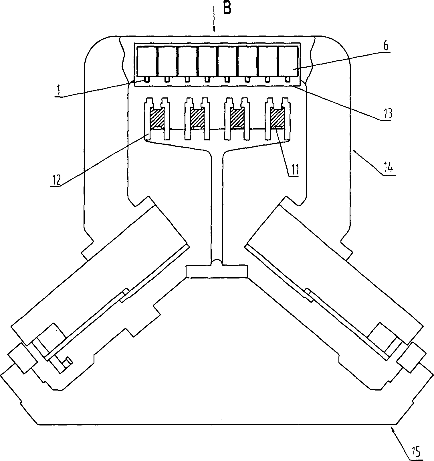
technical field [0001] The invention relates to a flat knitting machine, in particular to an electromagnet for controlling the shuttle box of the flat knitting machine. Background technique [0002] There are generally 4 shuttle bars at the upper center of the needle bed, and a number of shuttle boxes are respectively installed on the symmetrical sides of each shuttle bar. When weaving, the electromagnet operates according to the set program. The electromagnet drives the up and down movement of the bayonet by pushing the turning lever, and the bayonet drives the shuttle box to move on the shuttle bar or to be locked at a certain position. Each weaving system will control 8 rows of shuttle boxes on the symmetrical both sides on 4 shuttle bars. Therefore, generally each knitting system corresponds to 8 electromagnets, which are arranged in a row and installed in a special frame on the upper side of the flat knitting machine, and each electromagnet control corresponds to a row...

Claims


Application Information

Patent Timeline
IPC IPC(8): D04B15/00H01F7/08
Inventor 冯加林巫友群
Owner 冯加林
Why Eureka
Try Eureka