Supercharge Your Innovation With Domain-Expert AI Agents!

Pressure servo clutch power-assisted pump

A clutch and booster pump technology, which is applied in fluid-driven clutches, clutches, non-mechanical drive clutches, etc., can solve the problems of eccentric wear, unreasonable, non-following structure, etc., and achieve the effect of easy installation, reasonable structure, and overcoming eccentric wear

Inactive Publication Date: 2006-11-29
王庭义 +2
View PDF0 Cites 0 Cited by
  • Summary
  • Abstract
  • Description
  • Claims
  • Application Information

AI Technical Summary

Problems solved by technology

[0004] The purpose of the present invention is to provide a new type of clutch booster pump with spherical joint connection, full follow-up, reasonable structure and stable performance to improve driving The operator can control the clutch, which greatly eliminates the potential safety hazard caused by the failure of the booster pump

Method used


Image

  • Pressure servo clutch power-assisted pump

Examples


Embodiment Construction

[0039] The technical scheme of the present invention will be described in detail below in conjunction with the accompanying drawings.

[0040] Specifically, it is divided into non-working state and implementation assistance state:

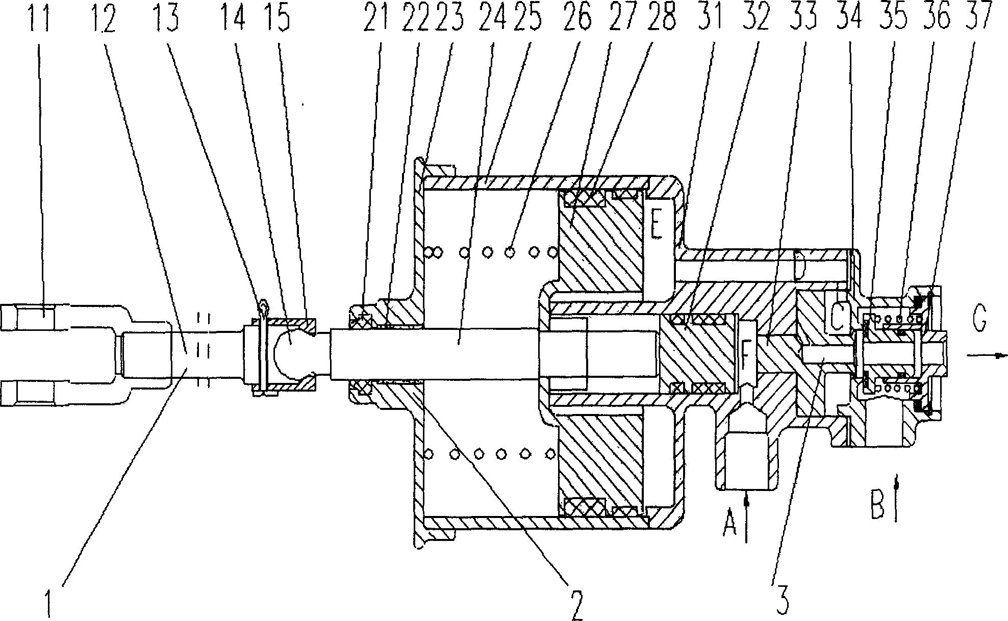
[0041] not working. When the driver does not step on the clutch, the device of the present invention does not work, so the oil pressure in the oil pressure chamber F is normal pressure, the oil cylinder piston 32 and the booster piston 27 are all in the return state at the right end, and the booster push rod 24 does not stretch out , the follower piston 33 is also in the return state at the left end, and the valve 35 in the small valve body 34 is compressed under the elastic force of the small spring 36, thereby cutting off the air inlet B.

[0042]Implement boost state. When the driver steps down the clutch pedal, the device of the present invention starts to work, and the hydraulic oil enters the hydraulic chamber F from the oil inlet A, and un...


PUM


Abstract

The invention relates to a pressure following up clutch assistant pump that includes front fork assembly, assistant cylinder assembly and back valve assembly. The push rod, assistant piston, cylinder piston, following up piston and valve are set on the same axis. The invention supplies assistant following up conception and designs the device. It realizes the real following up of trampling clutch footplate by driver and outputting assistant pump output by the corresponding enhancing relationship of driving force and liquid pressure formed by oil cylinder piston, following up piston, valve and small spring.

Description

Technical field [0001] The invention relates to an automobile pneumatic clutch booster, in particular to a clutch booster which is controlled by hydraulic pressure and boosted by compressed air. Background technique [0002] In order to reduce the driver's labor intensity and ensure driving safety, clutch booster pumps have been widely used in automobiles, especially in medium and heavy vehicles. In the existing clutch booster pump technology, hydraulic oil is generally used to control compressed air to increase the driving force of the booster pump to achieve the purpose. The existing technology generally relies on an external cable-pull return spring to pull the push rod to reset. Because the force of the return spring is not on the same center line as the reciprocating motion of the push rod and the piston, the piston and the inner wall of the booster pump cylinder are not aligned. Partial wear occurs between them, and oil and gas leakage occurs over time. In the prior ...

Claims


Application Information

Patent Timeline
IPC IPC(8): F15B15/02F16D25/00
Inventor 王庭义
Owner 王庭义
Features
  • R&D
  • Intellectual Property
  • Life Sciences
  • Materials
  • Tech Scout
  • Unparalleled Data Quality
  • Higher Quality Content
  • 60% Fewer Hallucinations
Learn More