Multistep assemblied anti-settle magnetic rheological damper

A magneto-rheological damper and assembled technology, which is applied in the field of damping devices, can solve the problems that it is difficult to effectively prevent the magnetorheological fluid from settling, and the requirements for DC current sources are high, so as to prevent static settling, increase output value, and process design simple effects

Inactive Publication Date: 2006-11-29
TIANJIN UNIV
0 Cites 17 Cited by

AI-Extracted Technical Summary

Problems solved by technology

At present, most of the magneto-rheological dampers in the domestic and foreign markets are designed with the piston and the piston rod integrated, and the controllable damping force is realized only by adjusting the magnetic field wi...

Abstract

The invention discloses a multi-step installation anti-settling magnetic current vibration altering absorber that includes cylinder, end cover, piston, and piston bar. Choking channel is set between the inner wall of the cylinder and the outside wall of the piston. Permanent magnetism piston plate covering on the piston bar is set between the two magnetic guiding piston discs. And exciting coil is set outside the magnetic guiding sleeve. The invention could be conveniently to install and could be repeatedly used. While power supply shutting down or energy is not abundant, the permanent magnetism piston plate would take place of magnetic loop to continue working and save energy. In non-working state, the permanent magnetism would avoid magnetic current liquid standing and depositing.

Application Domain

Technology Topic

PistonMagnetic current +4

Image

  • Multistep assemblied anti-settle magnetic rheological damper
  • Multistep assemblied anti-settle magnetic rheological damper
  • Multistep assemblied anti-settle magnetic rheological damper

Examples

  • Experimental program(1)

Example Embodiment

[0013] The present invention will be described in detail below in conjunction with the accompanying drawings and specific embodiments.
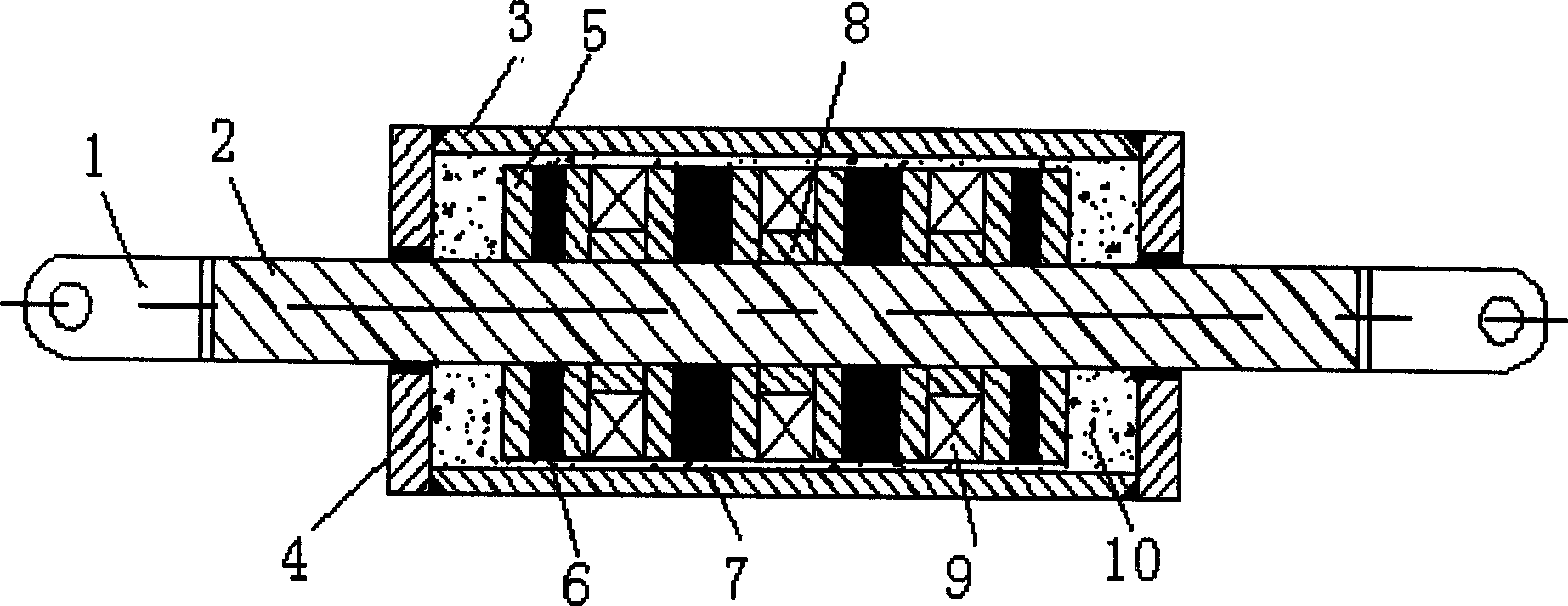
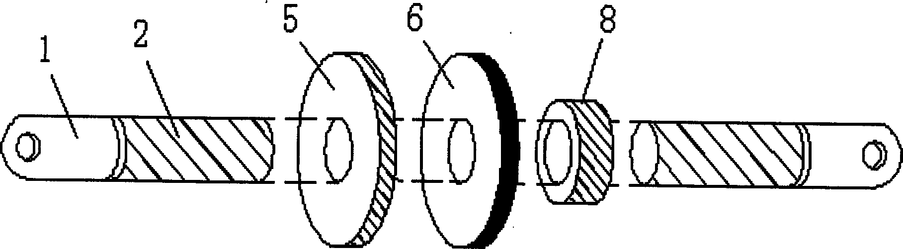
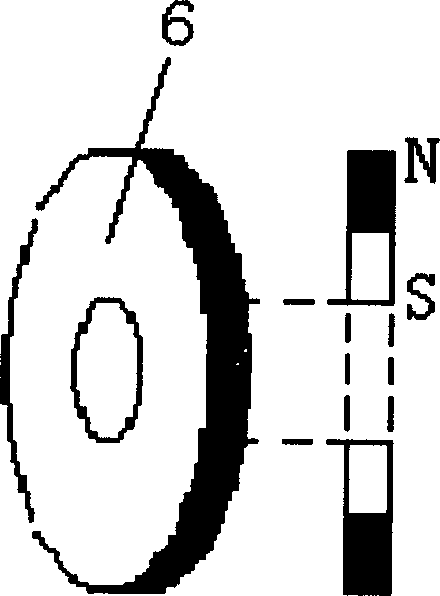
[0014] like Figure 1-3 The multi-stage assembled anti-settling magneto-rheological damper includes a cylinder 3, an end cover 4, a piston, a piston rod 2, and a throttling flow is arranged between the inner wall of the cylinder 3 and the outer wall of the piston. Road 7, the piston includes multiple groups of magnetically conductive piston disks that are sleeved on the piston rod 2 and each group is composed of two magnetically conductive piston disks 5, and the two magnetically conductive piston disks of each group of magnetically conductive piston disks There is a permanent magnet piston disc 6 set on the piston rod between them, and its magnetic strength is preferably 5000-8000 gauss. In order to increase its shear strength, its surface should have a high-strength coating, which can be zinc, nickel, etc. plating. A magnetic conduction sleeve 8 sleeved on the piston rod is arranged between the adjacent magnetic conduction piston discs of adjacent groups, and an excitation coil 9 is wound outside the magnetic conduction sleeve. When in use, earrings 1 can be assembled at both ends of the piston rod, and the cylinder barrel is filled with magnetorheological fluid 10 .
[0015] Working principle: When in use, the reciprocating external force at both ends of the damper pushes the piston rod 2, and the magneto-rheological fluid 10 in the chambers on both sides of the cylinder 3 will pass through the throttle channel 7, and a force perpendicular to the flow direction of the fluid is applied to the throttle channel area. During the magnetic field, the magnetorheological fluid 10 is semi-solidified, and the magnetic particles form chains along the direction of the magnetic field. Due to the existence of the permanent magnetic piston disc 6 in the present invention, the damping force is improved and the value range of the current is reduced; in addition, in the non-working state , since the permanent magnetic piston disc 6 can provide a fixed magnetic field, the magnetic particles in the magnetorheological fluid 10 continue to be arranged in chains along the direction of the magnetic field, effectively preventing the magnetorheological fluid from settling, image 3 The schematic diagram of the magnetization of the permanent magnet piston disc is shown, the magnetization direction is radial, and the N and S directions of the inner and outer edges can be set respectively according to actual needs.

PUM

PropertyMeasurementUnit
Magnetic strength5000.0 ~ 8000.0Gs
tensileMPa
Particle sizePa
strength10

Description & Claims & Application Information

We can also present the details of the Description, Claims and Application information to help users get a comprehensive understanding of the technical details of the patent, such as background art, summary of invention, brief description of drawings, description of embodiments, and other original content. On the other hand, users can also determine the specific scope of protection of the technology through the list of claims; as well as understand the changes in the life cycle of the technology with the presentation of the patent timeline. Login to view more.

Similar technology patents

Wear edge assembly

InactiveUS20050229442A1Effective wearEasy to disassembleSoil-shifting machines/dredgersEngineeringIncreased risk
Owner:ESCO CORP

Classification and recommendation of technical efficacy words

Why Eureka
Try Eureka