
Liquid-cooling heat sink

A liquid-cooled heat dissipation and heat-dissipating body technology, applied in instruments, electrical digital data processing, electrical components, etc., can solve problems such as waste of heat transfer methods, waste of driving horsepower, uneven heat transfer, etc.

Inactive Publication Date: 2006-11-29
FU ZHUN PRECISION IND SHENZHEN +1
View PDF0 Cites 18 Cited by
  • Summary
  • Abstract
  • Description
  • Claims
  • Application Information

AI Technical Summary

Problems solved by technology

[0009] Uneven heat transfer - due to the continuous heat accumulation of the coolant along the channel, the heat transfer effect of the coolant flowing through any area of ​​the heat absorbing plate is different, that is, the heat transfer of each area of ​​the heat absorbing plate is uneven, so the overall heat transfer is reduced efficacy
[0010] Poor turbulent flow effect—due to the uniform channel and smooth groove wall, the turbulent flow effect is poor
[0011] Waste of heat transfer—Since the center of the electronic heating element (such as CPU) is the hottest area and gradually decreases along its periphery, it is a waste of driving horsepower to transfer heat at a single high flow rate throughout the entire process, making the overall heat transfer of the heat absorbing plate Difficult to fully utilize

Method used


Image

  • Liquid-cooling heat sink
  • Liquid-cooling heat sink
  • Liquid-cooling heat sink

Examples


Embodiment Construction

[0026] The content of each form disclosed by the present invention will be described in detail below with specific examples.

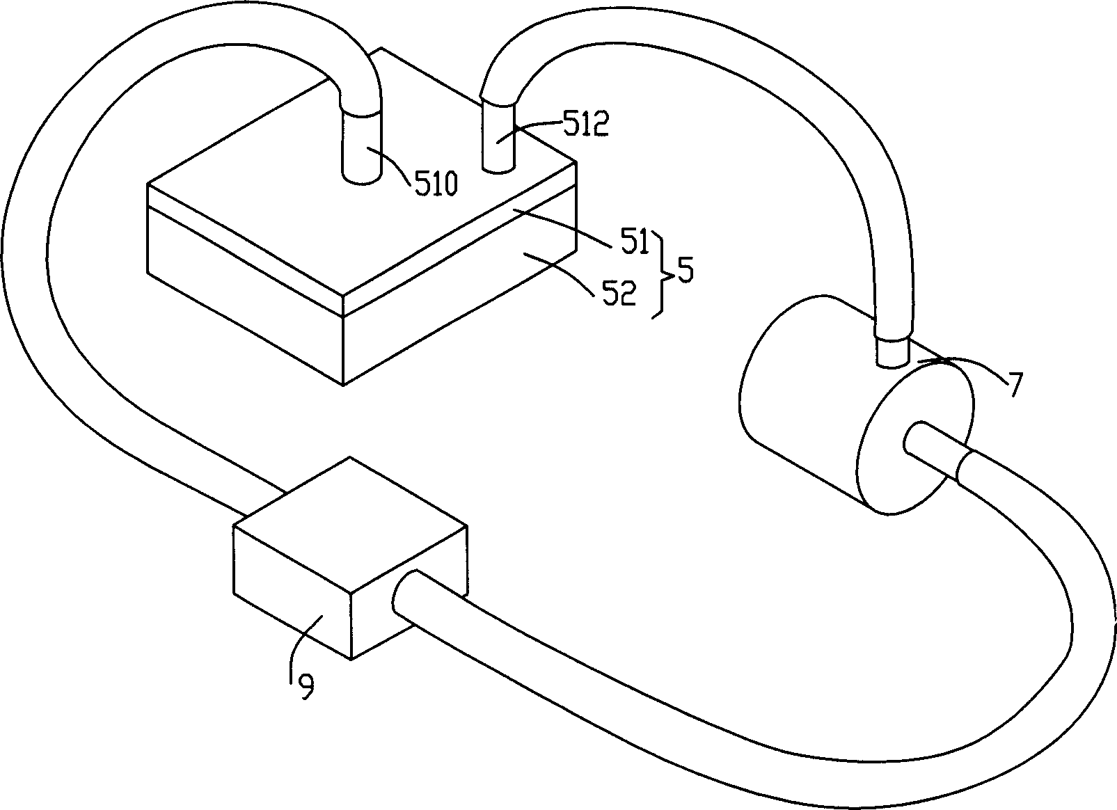
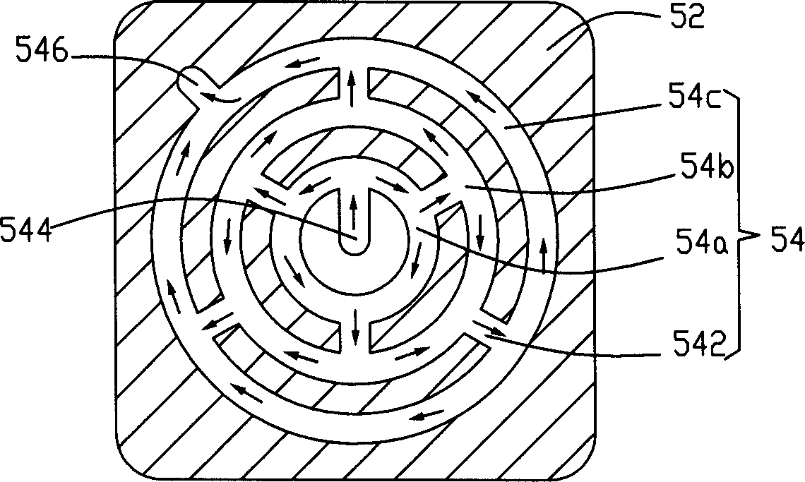
[0027] like figure 1 Shown is a schematic diagram of a first embodiment of a liquid cooling heat dissipation device. The liquid-cooled heat dissipation device includes a heat absorber 5, a heat sink 7 and a coolant driving device 9, the coolant drive device 9 can be a pump, which is used to drive the cooling liquid between the heat absorber 5 and the heat sink Cycle between 7. The heat absorber 5 includes an upper cover body 51 and a lower cover body 52 which are hermetically combined. The upper cover body 51 is provided with a liquid inlet pipe 510 at the central part, and a liquid outlet pipe 512 is provided at the side. The lower cover plate 52 faces the upper cover plate 51 side to excavate a groove to form a coolant channel 54 (such as figure 2 shown).

[0028] see figure 2 The coolant passage 54 includes a plurality of first concentric c...


PUM


Abstract

A heat radiation device with cooling liquid consists of a heat absorbing body, a heat radiation body, a cooling liquid channel and driving unit of cooling liquid. It is featured as connecting multiple passageway being arranged along heat absorbing body center to body periphery with channel of cooling liquid and connecting two adjacent passageways to each other, setting two branches leading to far point from heat absorbing body center on passageway near heat absorbing body center to let cooling liquid flow to passageway far from heat absorbing body center along two said branches.

Description

【Technical field】 [0001] The invention relates to a heat dissipation device, in particular to a liquid cooling heat dissipation device for cooling electronic components. 【Background technique】 [0002] At present, liquid cooling devices have been used in the industry to dissipate heat from electronic components such as computer central processing units. A liquid-cooled heat sink generally includes a circuit formed by a heat absorbing part, a heat sink and a pump. The circuit is filled with cooling liquid. The cooling liquid absorbs heat from the electronic components at the heat absorbing part and releases heat at the heat sink. Driven by the pump, the coolant circulates continuously in the circuit, thereby taking away the heat of the electronic components continuously. [0003] The cooling liquid channel of the heat absorber is a return channel connecting the inlet and outlet of the liquid cooling heat sink. The type of the heat absorber is usually to excavate a groove in ...

Claims


Application Information

Patent Timeline
IPC IPC(8): H01L23/473G06F1/20
Inventor 刘泰健李志鹏
Owner FU ZHUN PRECISION IND SHENZHEN
Learn More