Personal communication device with transmitted RF power strength indicator and method thereof

A technology for transmitting power and communication devices, which is applied in the field of personal communication devices, and can solve the problems that cellular mobile phones cannot be informed

Active Publication Date: 2006-11-29
VIA TECH INC
View PDF1 Cites 11 Cited by
  • Summary
  • Abstract
  • Description
  • Claims
  • Application Information

AI Technical Summary

Problems solved by technology

To this day, cellular mobile phone users still do not know these

Method used


Image

  • Personal communication device with transmitted RF power strength indicator and method thereof
  • Personal communication device with transmitted RF power strength indicator and method thereof
  • Personal communication device with transmitted RF power strength indicator and method thereof

Examples


no. 1 example

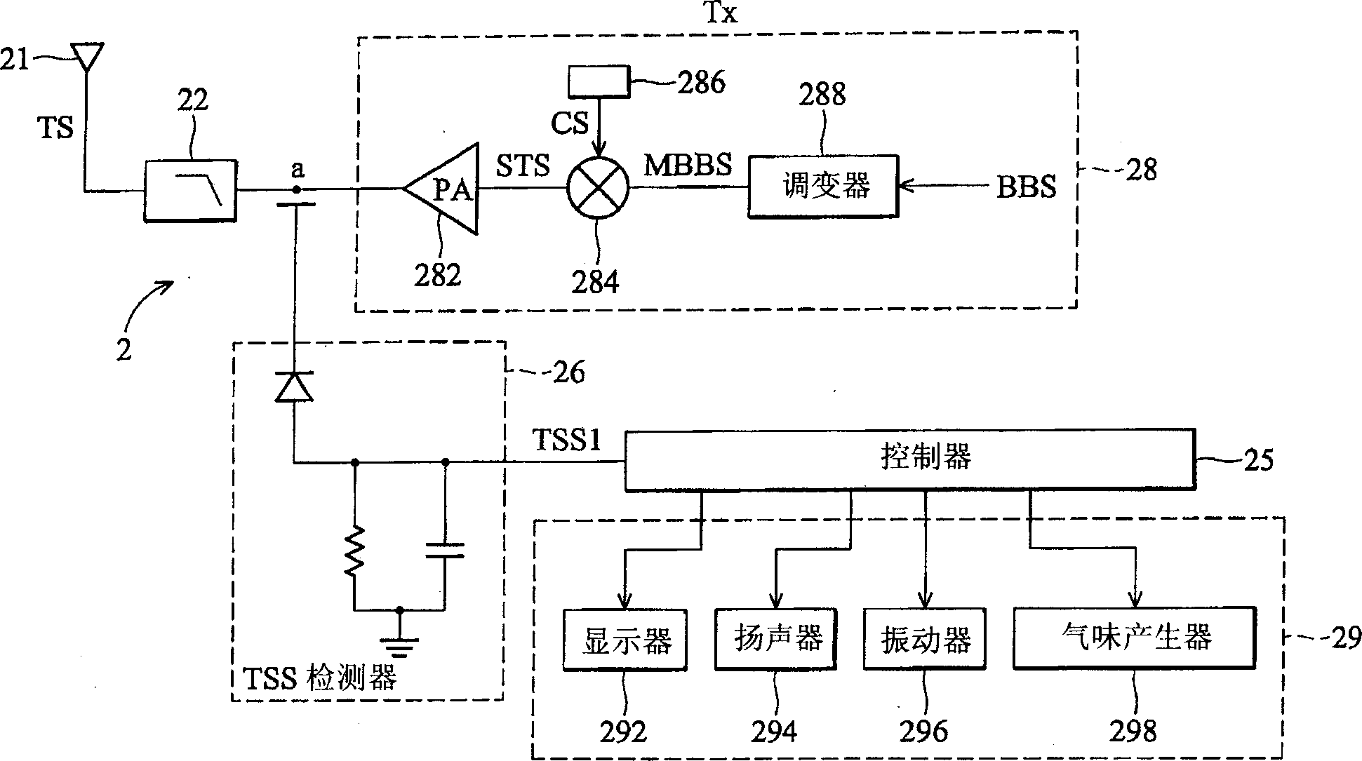
[0044] figure 2 A first embodiment of a personal communication device (PCD) having a transmit radio frequency (RF) power strength indicating circuit is shown. In general, the transmitter 28 can be composed of figure 2 , which includes a modulator 288 , a power amplifier 282 and a transmit radio frequency (RF) power detector 26 . The transmitted baseband signal BBS is modulated by the modulator 288, and then the signal MBBS output by the modulator is further processed and connected to the power amplifier 282, or the signal MBBS output by the modulator is directly connected to the power amplifier 282. The power amplifier 282, as its name implies, amplifies the power of the output signal. The amplified output signal is then filtered by filter 22 and sent to antenna 21 for transmission as a signal. A transmit radio frequency (RF) power detector (or called a transmit signal strength detector) detects the transmit signal strength TSS or the power of the amplified output signal...

no. 2 example

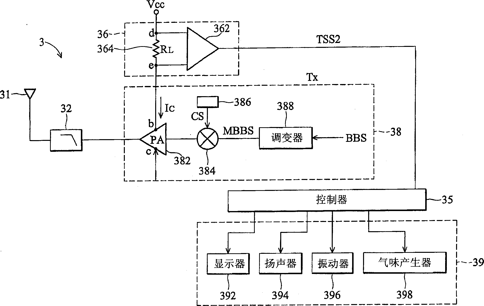
[0051] image 3 A second embodiment of the personal communication device (PCD) of the present invention is shown, which has a transmit radio frequency (RF) power strength indicating circuit. Except for the TSS detector 36, the second embodiment is similar to the first embodiment. Such as image 3 As shown, the transmit signal strength TSS can be determined by detecting the DC current consumption of the power amplifier (PA) 382 .

[0052] A transmit radio frequency (RF) power detector (or referred to as a transmit signal strength detector) 36 is used to detect transmit signal strength (TSS) levels. Once the transmission signal strength (TSS) is detected, the detection result TSS2 will be sent to the controller 35, and the controller will display the corresponding TSS state on the liquid crystal display (LCD) or large electronic display (LED), and the signal will be displayed in the form of smell, sound, etc. Send a user-programmable alarm signal to the user of the personal c...

no. 3 example

[0057] Image 6 A flow chart of steps for indicating transmit radio frequency (RF) power strength according to the present invention. The present invention also provides a method for indicating the transmit radio frequency (RF) power level status of a transmitter to alert a user of a personal communication device (PCD) to high radio frequency (RF) radiation. This method includes the following steps:

[0058] As shown in step 602 , an alarm level is preset for the transmit radio frequency (RF) power strength, ie transmit signal strength (TSS), represented by a decibel-milliwatt (dBm) unit, for example. Typically, mobile phone handsets using the pan-European digital mobile phone system (GSM) emit radio frequency (RF) radiation in the power range of -5 to 33 decibel milliwatts (dBm). Figure 5 Indicates that in the present invention, an alarm level is set for transmit radio frequency (RF) power strength. In this example, 10 decibel milliwatts (dBm) is used as the preset alarm ...


PUM


Abstract

A radio communication system for communication between a first mobile system and a second mobile system. Each mobile system has a transceiver for receiving and emitting radio signal. The second mobile system comprises a received signal strength detecting device, a power controller and an indicating device. The received signal strength detecting device detects a received signal strength of the transceiver in the second mobile system. The power controller outputs a transmitted power strength status and controls transmitted power of the transceiver according to the received signal strength. The indicating device receives the transmitted power strength status and indicates a transmitted RF power strength status of the transceiver in the second mobile.

Description

technical field [0001] The present invention relates to a radio communication system and method, in particular to a personal communication device (PCD) and method, which can indicate the radio communication terminal by outputting the power level of the transmitter of the radio communication terminal to an indicating device The transmitted radio frequency (RF) power strength level. Background technique [0002] AMPS, PHS, NADC, GSM, DCS, PCS, IS-95, CDMA, WCDMA, DECT, WLAN (802.11), DECT, CT0, CT1, etc., are well-known standards for wireless networks and personal communication devices (PCDs) . Personal communication devices include cellular phones, cordless phones, personal digital assistants (PDAs), portable walkie-talkies, smart mobile phones, and the like. All of the above personal communication devices are wireless communication devices (or radio communication devices). Communication links between PCDs are established by receiving and transmitting radio-frequency (radi...

Claims


Application Information

Patent Timeline
Patent Type & Authority Applications(China)
IPC IPC(8): H04B7/00H04B1/00H04B17/00H04Q7/20H04M1/00H04B1/04H04B1/38H04B7/005H04B7/26H04W52/10H04W52/52
CPCH04B1/3838H04B2001/3844H04W52/10H04W52/52
Inventor 施迪民陈淳杰何斌明
Owner VIA TECH INC
Why Eureka
Try Eureka