Method for controlling furnace temperature of heating furnace for continuous annealing

A control method and heating furnace technology, applied in heat treatment process control, heat treatment furnace, furnace, etc.

Inactive Publication Date: 2006-12-06
BAOSHAN IRON & STEEL CO LTD
View PDF3 Cites 18 Cited by
  • Summary
  • Abstract
  • Description
  • Claims
  • Application Information

AI Technical Summary

Problems solved by technology

Due to the large inertia and long delay characteristics of the furnace itself, coupled with the high-speed, continuous, and variable-specification process characteristics of continuous annealing, the traditional continuous annealing furnace temperature control cannot simultaneously meet the requirements of stability and rapidity.

Method used


Image

  • Method for controlling furnace temperature of heating furnace for continuous annealing
  • Method for controlling furnace temperature of heating furnace for continuous annealing
  • Method for controlling furnace temperature of heating furnace for continuous annealing

Examples


Embodiment Construction

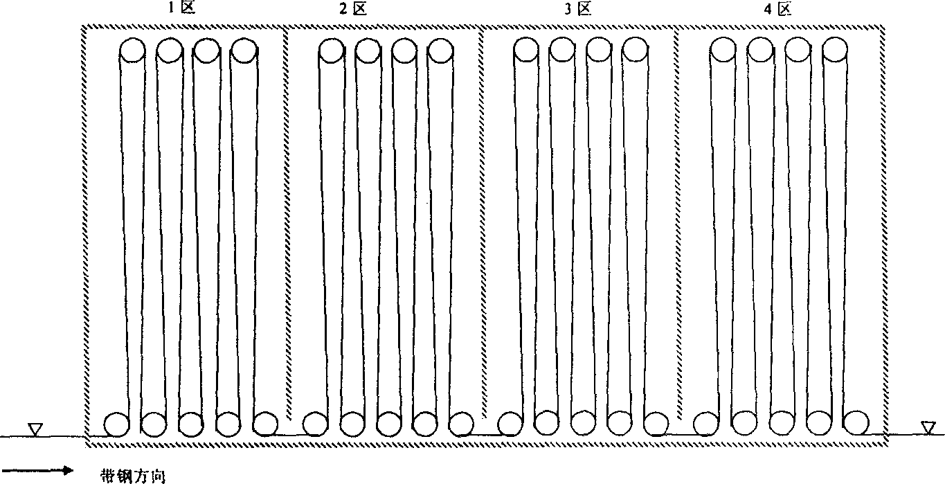
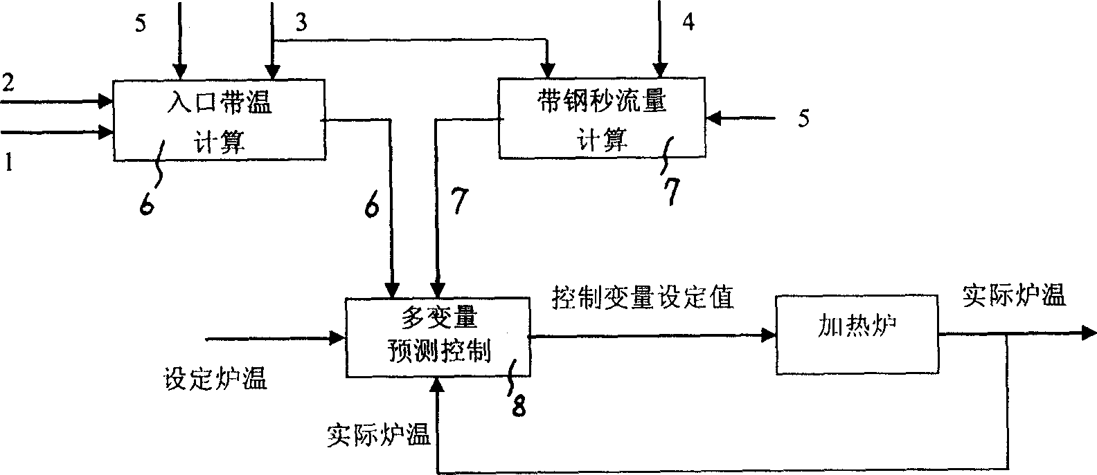
[0033] see figure 1 , image 3 , a furnace temperature control method for continuous annealing heating furnace, which takes the inlet strip temperature 6 of the furnace zone, the strip steel second flow 7 and the furnace temperature as input quantities, and uses the multivariable predictive control 8 algorithm to calculate the optimal gas at the current moment Flow increment, by adjusting the gas flow increment, the furnace temperature of the continuous annealing heating furnace is controlled, and the detailed description is as follows:

[0034] 1. Calculation of the entrance zone temperature 6, for the first furnace zone, the entrance zone temperature 6 can be measured by the zone temperature measuring instrument in front of the furnace, see figure 1 . For the follow-up furnace area, because it is very difficult to install a strip detector in the furnace, it can only be estimated based on the operating conditions of the former furnace area. The inlet zone temperature 6 of ...


PUM


Abstract

This invention relates to a method for controlling the temperature of continuous annealing heating oven. The entrance temperature of the oven, belt steel flow rate of a second and oven temperature are used as the input to calculate the optimal gas flow increase, and the oven temperature can be comtrolled by adjusting the gas flow increase. This invention considers the influences of belt steel thickness, width, flow rate and the entrance temperature to the oven temperature, and increases the accuracy and dynamic responsivity of the oven temperature control.

Description

(1) Technical field [0001] The invention relates to a furnace temperature control method for a continuous annealing heating furnace. (2) Background technology [0002] The structure of the continuous annealing heating furnace is as follows: figure 1 As shown, the whole furnace is divided into several zones, and there is an insulating wall between each zone to reduce the mutual interference of hot gas between furnaces. Each furnace area has independent control, such as: gas flow, voltage, power, etc., and furnace temperature measurement means. The existing continuous annealing heating furnace furnace temperature control generally adopts the single variable PID (proportional integral differential calculator) control method, see figure 2 , that is, the difference between the set furnace temperature and the measured furnace temperature is input, and the set value of the control variable is the output of the PID regulator. Due to the large inertia and long delay characteristi...

Claims


Application Information

Patent Timeline
Patent Type & Authority Applications(China)
IPC IPC(8): C21D11/00C21D9/56C21D1/26
Inventor 周坚刚胡广魁王海英
Owner BAOSHAN IRON & STEEL CO LTD
Why Eureka
Try Eureka