
Spray coating apparatus and spray coating method

A technology of spraying device and spraying direction, which is applied to spraying device, spraying device, spraying discharge device and other directions, can solve the problems of unpractical spraying, disordered pattern, change of atomization angle, etc.

Inactive Publication Date: 2006-12-06
NIPPON PAINT CO LTD +1
View PDF0 Cites 14 Cited by
  • Summary
  • Abstract
  • Description
  • Claims
  • Application Information

AI Technical Summary

Problems solved by technology

[0014] In this way, attempts have been made to supply air from the rear of the nozzle of the spraying machine to the front periphery, prevent paint from scattering, adjust the supplied air, and ease the air conditioning of the spray booth. The atomization angle of paint particles changes, the pattern of spraying is chaotic, and the spraying itself causes problems, so it cannot be practical

Method used


Image

  • Spray coating apparatus and spray coating method
  • Spray coating apparatus and spray coating method
  • Spray coating apparatus and spray coating method

Examples


Embodiment Construction

[0124] Embodiments of the present invention will be described below in conjunction with the accompanying drawings. But it does not constitute any limitation to the present invention.

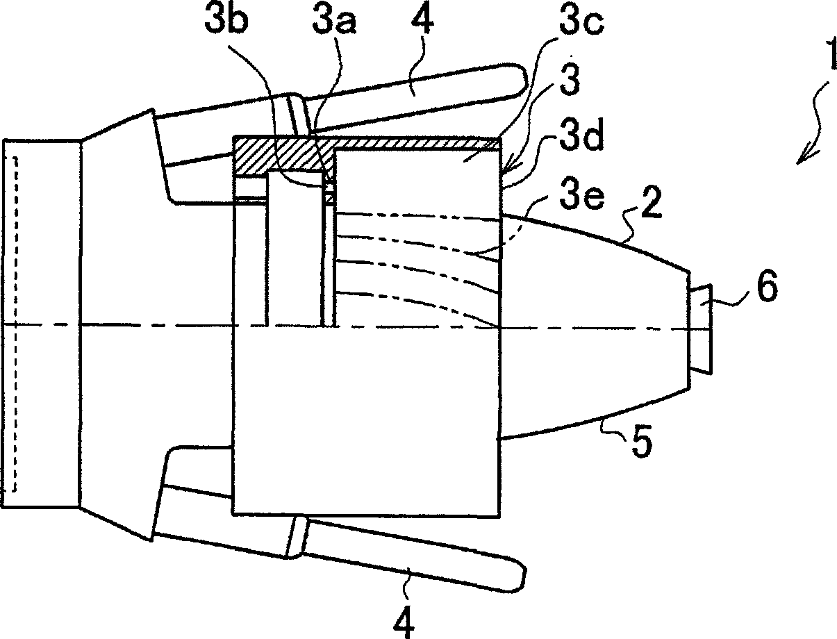
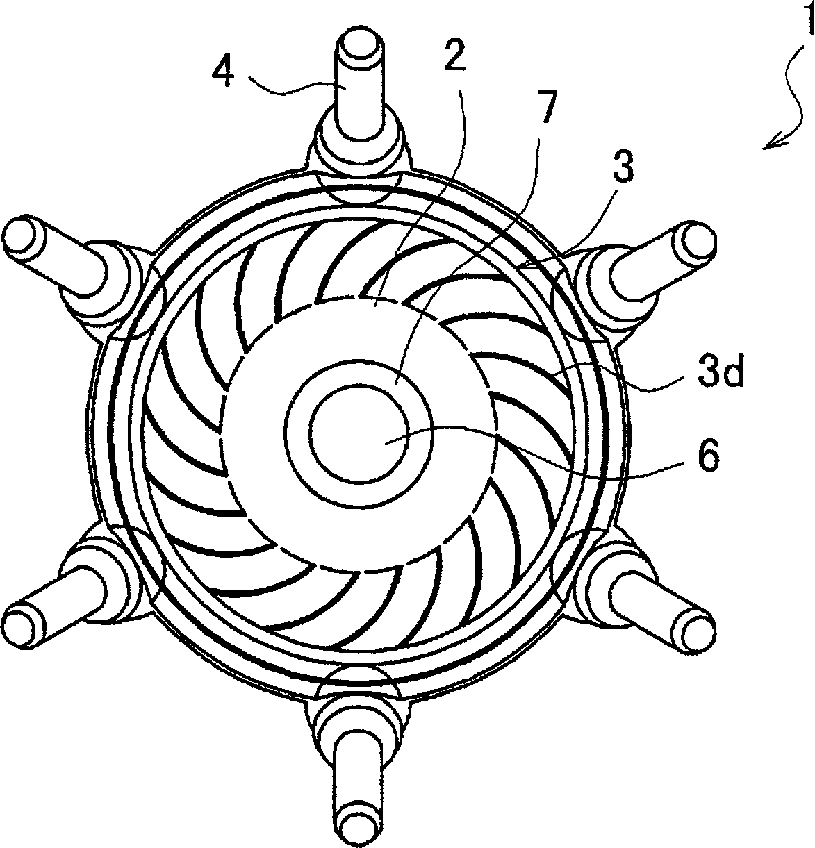
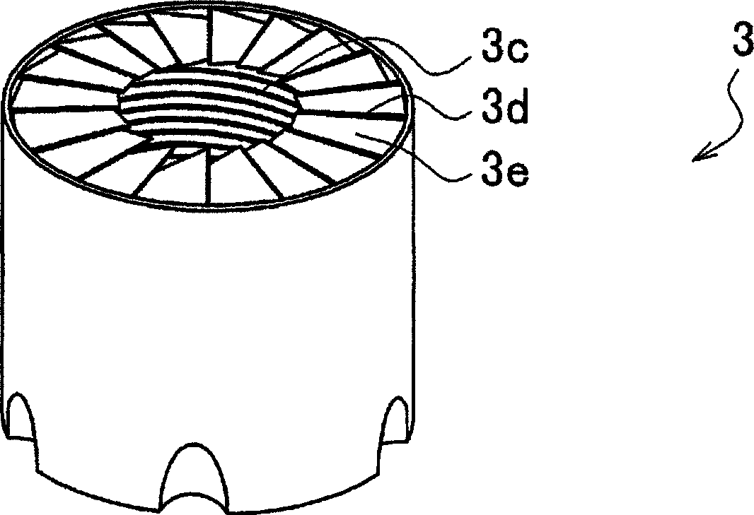
[0125] figure 1 is a partial sectional side view of the first embodiment of the spraying device of the present invention, figure 2 yes figure 1 Fig. 3 is a first distributor provided in the first embodiment, (a) is a perspective view, (b) is a front view, and (c) is a bottom view. However, in these drawings, dimensions are appropriately adjusted for easy understanding.

[0126] Spraying device 1 of the present invention, as figure 1 and figure 2 As shown, it is mainly composed of a sprayer body 2 , a first distributor 3 and a plurality of electrodes 4 (six in this embodiment). The main body 2 of the spraying machine is, for example, made of an insulating material such as polytetrafluoroethylene, which is formed by forming a cylindrical sleeve, and a nozzle 6 is provided at its front end,...


PUM


Abstract

By forming an air flow in which a quantity and a blowoff angle of the air supplied toward an atomized spray paint flow don't influence a coating pattern, there are provided a coating apparatus and a coating method, each of which does not disturb the coating pattern, does not require conditions such as wind speed and temperature of a conventional coating booth, and can perform remarkable reduction in an air conditioning energy of the coating booth, prevention of scatter of a paint, and an improvement in a paint adhesion efficiency. In a spray coating apparatus which possesses a casing and an injection nozzle provided in a tip side of the casing and which forms a coating pattern by injecting paint and shaping air from the injection nozzle to thereby form a coating film on a coated object, a first adapter which blows off the air in an injection direction of the injection nozzle is provided on a substantially concentric circle of the injection nozzle, and the first adapter covers, by blowing off the introduced air while giving it a blowoff angle slanting toward a circumferential direction, an outer periphery of the coating pattern near the injection nozzle with the air.

Description

technical field [0001] The invention relates to an atomizing spraying device and a spraying method for spraying automobiles and building outer packages, in particular to greatly reducing the energy of regulating air during spraying, preventing paint from scattering, and improving the coating rate. Background technique [0002] In the past, attempts were made to prevent the paint from scattering by forming air that deflects the paint particles atomized by the spray toward the direction of the object to be sprayed, by adjusting the temperature and humidity of the supplied air for air conditioning, and by promoting the removal of solvents such as water in the paint. The volatilization can achieve the purpose of easing the air conditioning of the spray booth. For example, as shown in Patent Document 1 (Patent Publication No. 2000-325860), it is proposed that in the electrostatic spraying method of spraying paint with a rotary atomizing sprayer with an external electrode, in orde...

Claims


Application Information

Patent Timeline
Patent Type & Authority Applications(China)
IPC IPC(8): B05B1/28B05B1/34B05D1/02B05D1/04B05B5/04B05B5/053B05B7/06B05B7/08B05B7/16B05B12/10B05B15/12
CPCB05B7/0815B05B5/0533B05B15/12B05B5/001B05B7/16B05B5/0407B05B12/10B05B5/0426B05B16/00
Inventor 平野克巳竹下胜启金仓显博山崎谕志
Owner NIPPON PAINT CO LTD
Learn More