
Tire sensor device and tire information transmission method

A sensor device and sensor technology, used in tire measurement, tire parts, instruments, etc., can solve problems such as short battery life and achieve the effect of improving service life

Inactive Publication Date: 2006-12-06
BRIDGESTONE CORP
View PDF3 Cites 5 Cited by
  • Summary
  • Abstract
  • Description
  • Claims
  • Application Information

AI Technical Summary

Problems solved by technology

[0003] However, since the above-mentioned battery-driven tire pressure sensor terminal 80 has a transmitter 85 for transmitting the above-mentioned tire pressure information to the vehicle body in addition to the analog amplifier 82 and the processing circuit 83, the battery life is relatively short. The tire pressure sensor terminal 80 above needs to be replaced periodically

Method used


Image

  • Tire sensor device and tire information transmission method
  • Tire sensor device and tire information transmission method
  • Tire sensor device and tire information transmission method

Examples


Embodiment approach 1

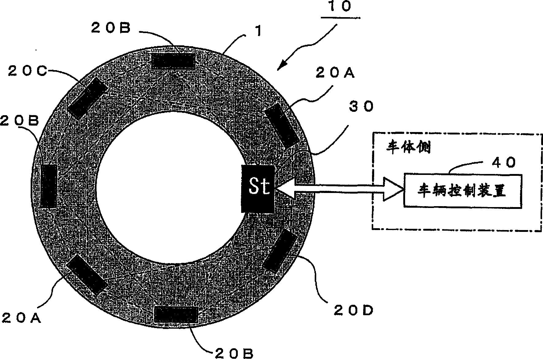
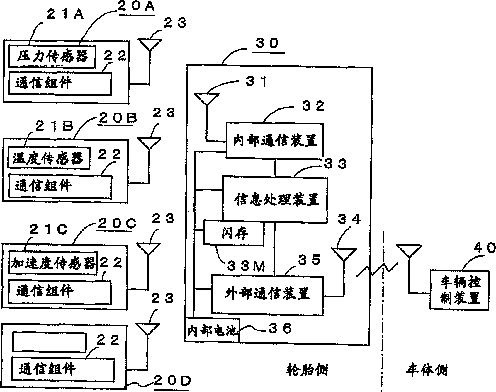
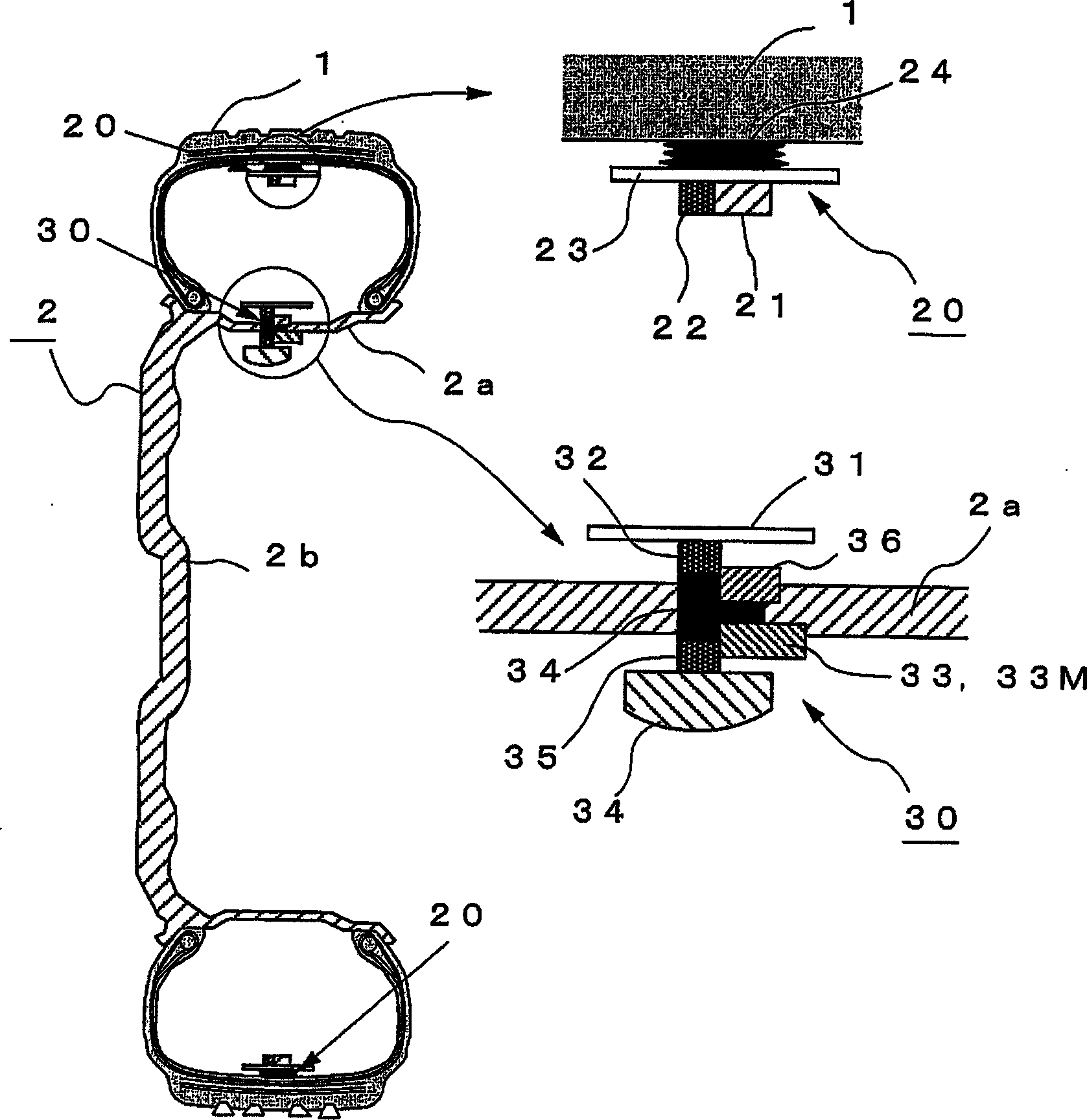
[0087] figure 1 It is a diagram schematically showing a method of transmitting tire information in the first preferred embodiment. figure 2 It is a functional block diagram showing the configuration of the tire sensor device. image 3 It is a figure showing the installation state of the said tire sensor device. In each figure, 1 is a tire; 2 is a wheel composed of a rim 2a and a wheel 2b; 10 is a tire sensor device having a plurality of sensor units 20 (20A to 20D) mounted on the above-mentioned tire 1; and The base station 30, which together with the sensor unit 20 constitutes a tire intra-network (hereinafter referred to as the tire intra-local area network) and processes tire information signals from the sensors 21 (21A-21C) of the sensor unit 20, sends the signal to the vehicle body Side transmission; 40 is a vehicle control device arranged on the side of the vehicle body.

[0088] The sensor assembly 20 has a sensor, and a communication mechanism equivalent to an RFI...

Embodiment approach 2

[0110] In the above preferred embodiment 1, the sensor unit 20 and the base station 30 constitute an in-tire network, and each sensor device (sensor unit 20) is provided with a power regeneration circuit for receiving radio waves sent from the base station 30 and generating and driving each However, if the power supply to each sensor device is changed from the base station 30 to the vehicle body side, the tire sensor device can be made smaller and more power-saving.

[0111] Figure 4 It is a diagram schematically showing a method of transmitting tire information in the second preferred embodiment. Figure 5 It is a functional block diagram showing the structure of the tire sensor device of this example. Figure 6 It is a figure showing the installation state of the said tire sensor device. In each figure, 1 is a tire, 2 is a wheel including a rim 2a and a wheel disc 2b, and 50 is a tire sensor device, which has a plurality of sensor units 60 (20A to 60C) installed at specif...


PUM


Abstract

In a tire, there are arranged a plurality of sensor modules (20A-20D) each including a sensor, a communication module having a communication function and a power regeneration circuit, and an antenna; and a base station (30) including an internal communication device for performing communication with the sensor modules (20A-20D), an information processing device for processing tire information signals from the sensor modules, an external communication device for communicating with a vehicle control device (40) of the vehicle body side, and a power source. The sensor modules (20A-20D) and the base station (30) constitute an in-tire LAN. Tire information signals transmitted from the sensor modules (20A-20D) are processed at the base station (30) and transmitted to a vehicle control device (40). Thus, it is possible to obtain appropriate tire information while reducing the size of the sensor device and power consumption.

Description

technical field [0001] The present invention relates to a tire sensor device that collects and processes information from various sensors mounted on tires, and transmits the processed information to a vehicle body side, and a tire information transmission method. Background technique [0002] In the past, a tire pressure monitoring device has been put into practical use. In this tire pressure monitoring device, a pressure sensor device for detecting the pressure of the gas filled in the tire is installed, for example, on the surface of the wheel facing the tire cavity area. It detects the internal pressure of the tire and sends the information to the vehicle body side, thereby notifying the driver of the internal pressure state of the tire. 8( a ) is a block diagram showing the structure of a tire pressure sensor terminal 80 as a conventional pressure sensor device. The tire pressure sensor terminal 80 has: an air pressure sensor 81 that detects the internal pressure of the ...

Claims


Application Information

Patent Timeline
IPC IPC(8): G08C17/02B60C23/04B60C23/20
Inventor 市川洋光羽田裕昌国分孝夫奥雅春丰福雅宣
Owner BRIDGESTONE CORP
Learn More