Infrared gas analyzer with hollow fiber resonant cavity
A technology of gas analyzer and resonant cavity, which is applied in the direction of color/spectral characteristic measurement, etc., can solve the problems of large size and bulky gas chamber, and achieve the effect of increasing the length of the optical path, increasing the sensitivity, and reducing the space
- Summary
- Abstract
- Description
- Claims
- Application Information
AI Technical Summary
Problems solved by technology
Method used
Image
Examples
Embodiment 1
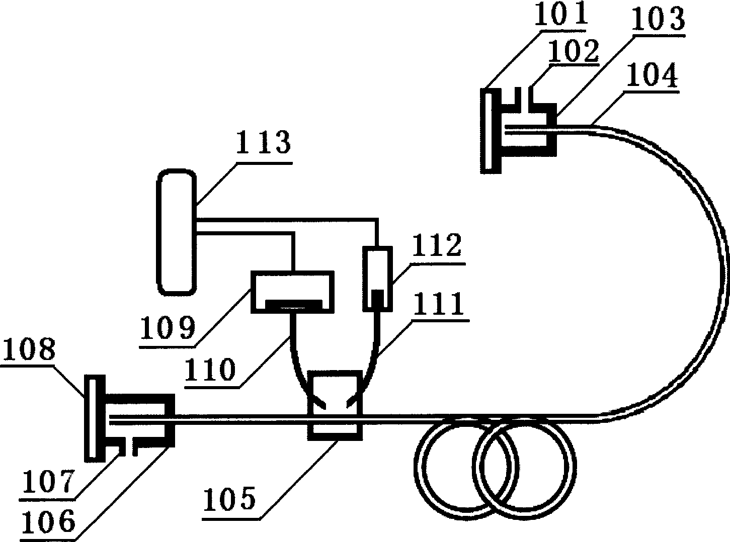
[0011] Such as figure 1 As shown, one end of the hollow gas path fiber 104 is connected to the inlet fiber connection unit 103, and corresponds to the position of the reflector 101. The probe light transmitted from the gas path fiber 104 is reflected by the reflector 101 and then transmitted In the gas path optical fiber 104. The air inlet fiber optic connector 103 is hollow and provided with an air inlet 102 , through which the gas to be measured flows into the air inlet fiber optic connector 103 , and further flows into the air path optical fiber 104 .
[0012] The other end of the hollow gas path fiber 104 is connected to the outlet fiber optic connector 106 and corresponds to the position of the reflector 108. The detection light transmitted from the gas path fiber 104 is reflected by the reflector 108 and then enters the gas path fiber 104 middle. The gas outlet fiber optic connector 106 is hollow and provided with a gas outlet 107 through which the gas to be measured f...
Embodiment 2
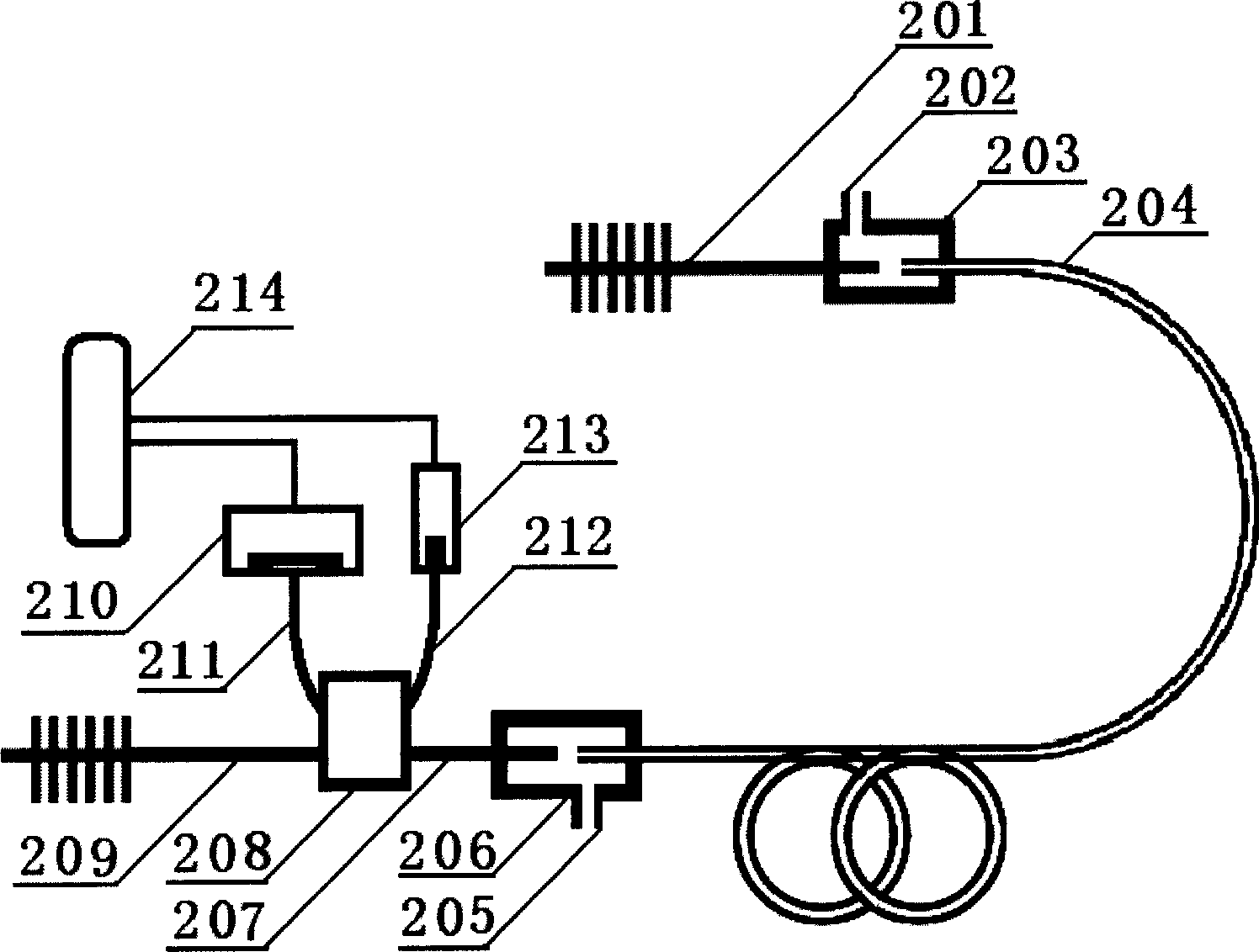
[0016] Such as figure 2 As shown, the fiber grating 201 is connected to the intake fiber connector 203, and one end of the hollow gas path fiber 204 is also connected to the gas path fiber connector 203, and the position of the fiber grating 201 corresponds to the gas path fiber 204, and the gas path The probe light transmitted from the optical fiber 204 is reflected by the fiber grating 201 and then enters the air path optical fiber 204 . The air inlet fiber optic connector 203 is hollow and is provided with an air inlet 202 , through which the gas to be measured flows into the air inlet fiber optic connector 203 and further flows into the air path optical fiber 204 .
[0017] The other end of the hollow air path optical fiber 204 is connected to the air outlet optical fiber connector 206, and one end of the connecting optical fiber 207 is also connected to the air outlet optical fiber connector 206. The port position of the connecting optical fiber 207 corresponds to the po...
PUM
 Abstract
Description
Claims
Application Information
 - R&D
- Intellectual Property
- Life Sciences
- Materials
- Tech Scout
- Unparalleled Data Quality
- Higher Quality Content
- 60% Fewer Hallucinations
Browse by: Latest US Patents, China's latest patents, Technical Efficacy Thesaurus, Application Domain, Technology Topic, Popular Technical Reports.
© 2025 PatSnap. All rights reserved.Legal|Privacy policy|Modern Slavery Act Transparency Statement|Sitemap|About US| Contact US: help@patsnap.com


