Power factor corrector

A power factor correction and coil technology, applied in the direction of output power conversion devices, transformers, inductors, etc., can solve the problems of raw material waste, magnetic line interference, increase raw material cost, etc., to reduce noise and low-frequency continuous wave interference, improve heat dissipation Efficiency, the effect of reducing the magnetic leakage phenomenon

Inactive Publication Date: 2006-12-13
陈 球南
View PDF0 Cites 1 Cited by
  • Summary
  • Abstract
  • Description
  • Claims
  • Application Information

AI Technical Summary

Problems solved by technology

[0004] The U-shaped iron core 10 of a commonly used power factor corrector is composed of U-shaped silicon steel sheets 111 in a stacked manner to form a U-shaped silicon steel block 11, and then two U-shaped silicon steel blocks 11 pass through the coil in a relatively joint manner. The structure of the U-shaped silicon steel block 11 is formed by stacking each silicon steel sheet 111 on top of each other. Each silicon steel sheet 111 is formed by stamping. Among them, a large amount of waste will be generated, which not only causes waste of raw materials, but also increases the cost of raw materials when the supply of silicon steel sheets is in short supply. In addition, during assembly, it is very easy to be damaged due to the quality of silicon steel sheets or negligence in the assembly process Slots in the coil structure, causing damage to the insulating coil and becoming a defective product
[0005] The power factor corrector is a high-sensitivity magnetic component, and the general loss often occurs in the "copper loss" or "iron loss" part. The magnetic field lines of the commonly used U-shaped silicon steel sheet structure are from the inside to the outside. When the space cannot be closely combined, magnetic resistance and layer gap capacitance will be generated, and in the case of extremely fast flux leakage, the heat dissipation will slow down when the magnetic circuit between the silicon steel sheets is incomplete, which will affect the electrical device used. cooling effect; see figure 2 , the coil structure of the power factor corrector is that the thick-diameter coil 21 and the thin-diameter coil 22 are arranged in a coil package 20 at the same time, and then the coil package 20 with the thick-diameter coil 21 is connected with the coil package 20 with the thin-diameter coil 22 Corresponding to the configuration, such a coil structure will cause interference between the magnetic lines of force between the coils, resulting in serious magnetic flux leakage

Method used


Image

  • Power factor corrector
  • Power factor corrector
  • Power factor corrector

Examples


Embodiment Construction

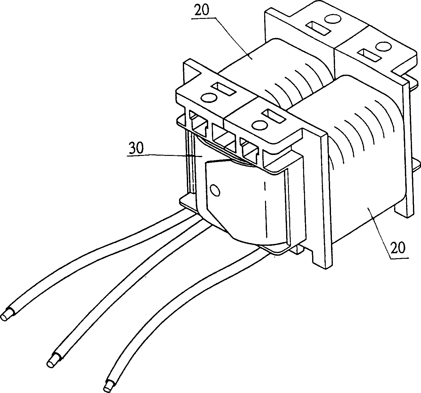
[0018] see image 3 , Figure 4 As shown in Fig. 5, a power factor corrector, the iron core enclosed in the coil package 20 is a coiled iron core 30, and the entire iron core 30 is basically wound with a steel strip 311 to form an inner ring type Egg-shaped body 31, the egg-shaped body 31 is cut into two symmetrical combined blocks 32, and the two combined blocks 32 are inserted into the coil 20 structure of the power factor corrector in a docking manner to form a complete The iron core 30 is constructed and assembled with the coil package 20 to form a power factor corrector.

[0019] Among them, the egg-shaped body 31 used to form the iron core 30 is formed by winding silicon steel strips, so the waste of materials can be greatly reduced, and the cost can be effectively reduced. The coil body formed by the package 20 is relatively easy to assemble, which can effectively reduce the generation of defective products, and the generated magnetic crystals have a non-directional s...


PUM


Abstract

The invention discloses a power factor corrector, which consists of iron core and coil bulk, wherein the iron core is composed of two cut symmetrical combination blocks of inner-ring typed egg-shaped bulk winded by steel band; the coil body is composed of coil bag with rough diameter coil and thin diameter coil; two symmetrical combination blocks are plugged in the coil bulk through butting pattern. The invention saves material with excellent radiation property, which reduces magnetic leakage phenomenon.

Description

technical field [0001] The invention relates to a power factor corrector, in particular to a power factor corrector with a coiled iron core and a thick diameter coil and a thin diameter coil interlacedly wound on the iron core. Background technique [0002] In the prior art, passive components such as inductors are often used in chassis power supplies used in electrical devices such as personal computer hosts or servers to control or adjust the time and waveform of the AC current input so that it is as close as possible to the DC voltage waveform. It may be consistent to help the electrical device used to improve the efficiency of its own energy use. This effect is the so-called power factor correction (Power FactorCorrection, PFC). [0003] see figure 1 , which is a commonly used power factor corrector. A similar power factor corrector is composed of a coil package 20 wound on a U-shaped iron core 10. Since electricity and magnetism can be converted to each other, the curr...

Claims


Application Information

Patent Timeline
Patent Type & Authority Applications(China)
IPC IPC(8): H01F27/25H01F27/28H01F38/00H02J3/01H02M1/12
CPCY02E40/40
Inventor 陈球南
Owner 陈 球南
Why Eureka
Try Eureka