
Expansion tank device, process for fabricating expansion tank device, and liquid cooling radiator

A technology of expansion tank and radiator, which is applied to household refrigeration devices, cooling fluid circulation devices, electric solid devices, etc., can solve the problems of low cooling efficiency of radiators, air returning to the spare box, etc.

Inactive Publication Date: 2006-12-13
SHOWA DENKO KK +1
View PDF1 Cites 3 Cited by
  • Summary
  • Abstract
  • Description
  • Claims
  • Application Information

AI Technical Summary

Problems solved by technology

However, with the radiator disclosed in the above publication, when the display unit is closed, the air in the spare box enters the circulation pipe, and when the display unit is opened, it is difficult to return the air to the spare box, so that the radiator has a problem of low cooling efficiency.

Method used


Image

  • Expansion tank device, process for fabricating expansion tank device, and liquid cooling radiator
  • Expansion tank device, process for fabricating expansion tank device, and liquid cooling radiator
  • Expansion tank device, process for fabricating expansion tank device, and liquid cooling radiator

Examples


Embodiment Construction

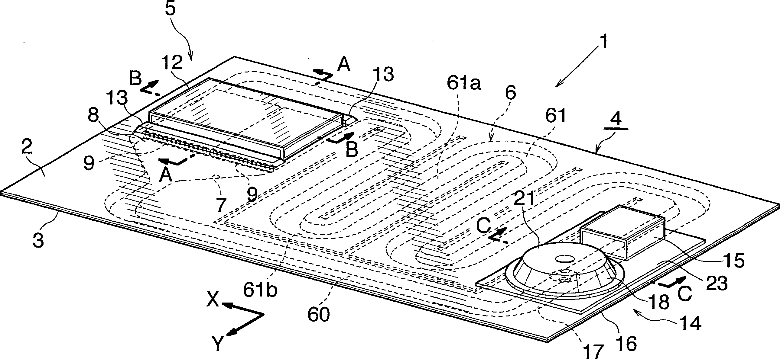
[0079] Embodiments of the present invention will be described below with reference to the drawings. In the instructions below, figure 1 The direction indicated by an inner arrow X will be referred to as "left" and the opposite direction will be referred to as "right", and the direction indicated by an arrow Y within the same drawing will be referred to as "front" and the opposite direction will be referred to as "rear".

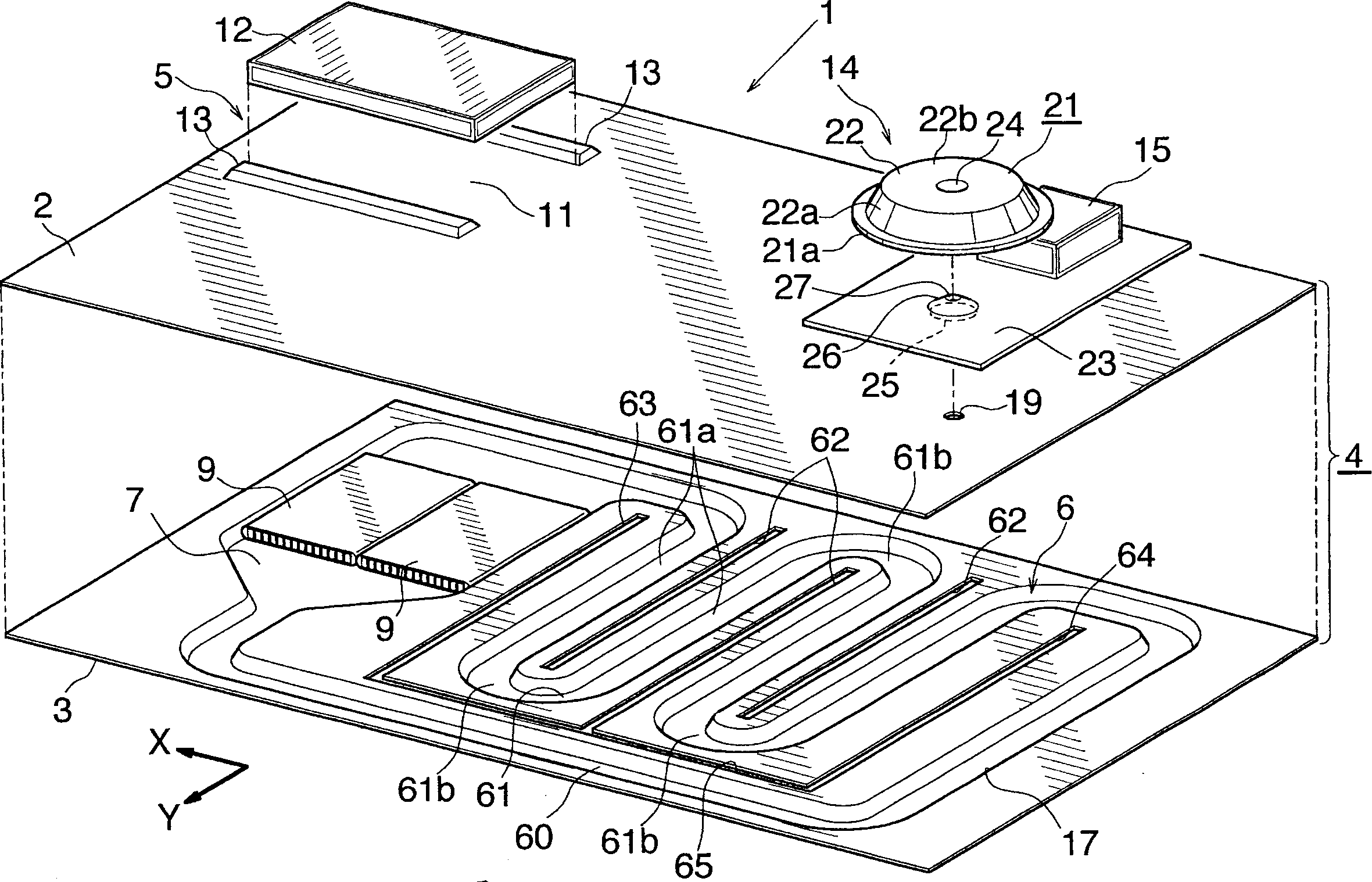
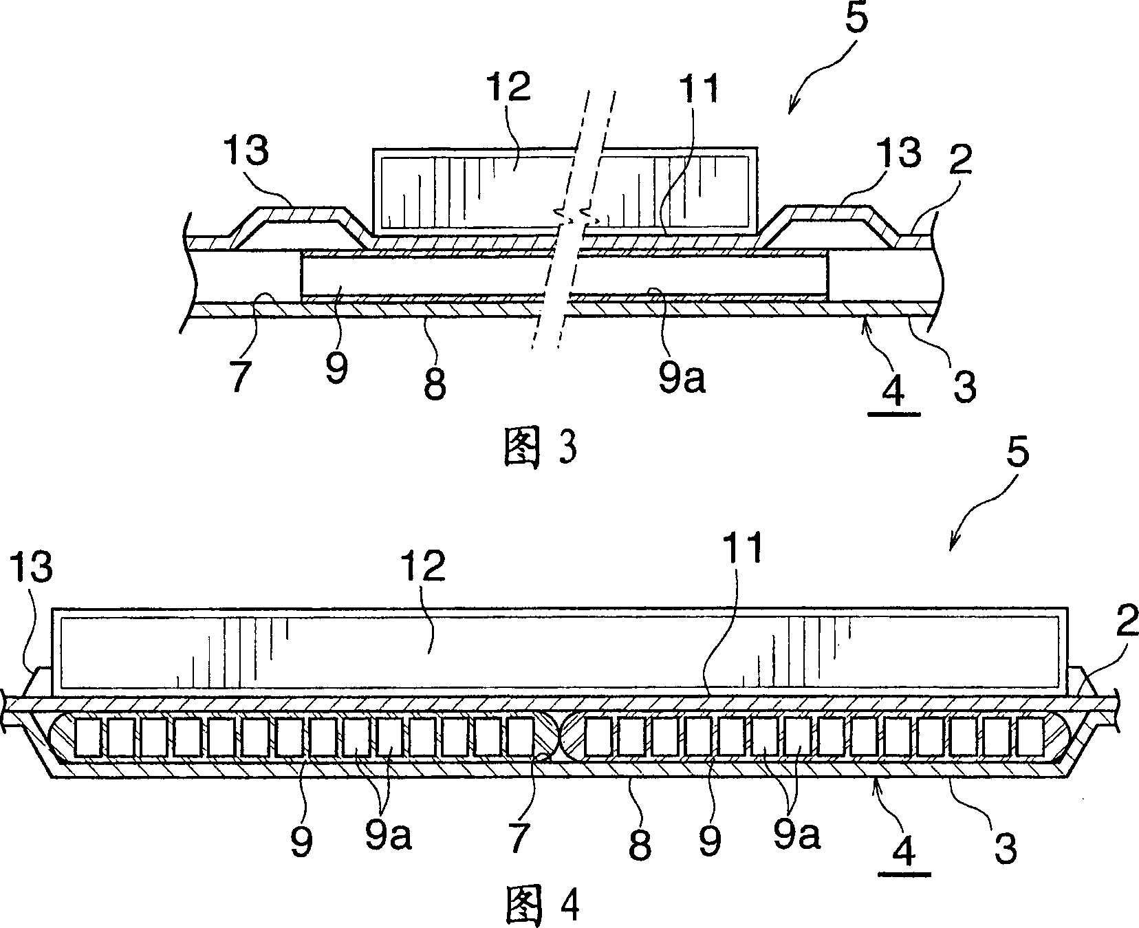
[0080] figure 1 and figure 2 Showing the overall structure of a liquid-cooled radiator embodying the present invention having an expansion tank device, FIGS. 3 to 7 show the structure of the main part of the radiator. Figure 8 and 9 A method of manufacturing the heat sink is shown.

[0081] refer to figure 1 and 2 , The liquid-cooled heat sink 1 has a rectangular substrate 4 elongated left and right, which is composed of two high thermal conductivity plates such as aluminum plates 2, 3 at the upper and lower sides overlapped and combined with each oth...


PUM


Abstract

An expansion tank device 14 comprises a tank installation base 16 having a cooling liquid channel 17 and an expansion tank 18 provided on the upper surface of the installation base 16. The base 16 has a communication hole 19 for holding space above the upper surface thereof in communication with the cooling liquid channel 17. The expansion tank 18 has a tank main body 21 including an upwardly bulging portion 22 having an opening at its lower end, and a bottom plate 23 joined to the lower end of the tank main body 21 for closing the lower-end opening of the bulging portion 22 and joined to the upper surface of the tank installation base 16. The bottom plate 23 is provided at a portion thereof corresponding to the communication hole 19 with a through hole 25 communicating with the communication hole 19. The bottom plate 23 is provided with a baffle plate 26 formed along the entire circumference of the inner peripheral edge thereof defining the through hole 25 and slanting upwardly toward the center of the through hole 25. The expansion tank device 14 removes the air in the cooling liquid from the circulating system, precludes the system from breaking and prevents the decrease in the amount of cooling liquid within the circulating system.

Description

[0001] Cross References to Related Applications [0002] This application is an application filed pursuant to 35 U.S.C. §111(a) and filed pursuant to 35 U.S.C. §119(e)(1) on November 17, 2003, November 17, 2003, and August 2004 3 filing date benefit of provisional applications Nos. 60 / 520,281, 60 / 520,282 and 60 / 598,050 filed pursuant to 35 U.S.C. § 111(b). technical field [0003] The present invention relates to an expansion tank arrangement for use in a device for dissipating heat generated by a heat source, a method of manufacturing the expansion tank arrangement, and a liquid-cooled radiator having the expansion tank arrangement, wherein the The heat source is provided in IT equipment such as personal computers and servers, AV equipment, industrial machines, machine tools, and the like. [0004] The term "aluminum" as used herein and in the appended claims includes aluminum alloys in addition to pure aluminum. In addition, the terms "upper" and "lower" refer to figure 1...

Claims


Application Information

Patent Timeline
IPC IPC(8): F25D17/02H05K7/20H01L23/50
Inventor 片田好纪多贺和夫
Owner SHOWA DENKO KK
Learn More