Planetary gear type reduction gear with torque limiter

A technology of torque limiter and planetary gear, applied in belt/chain/gear, gear transmission, mechanical equipment, etc., can solve the problems of large rotating torque and the inability of universal torque limiter mechanism, to eliminate The effect of fluctuation, simple torque adjustment, and stable transmission torque

Inactive Publication Date: 2006-12-20
TOK BEARING CO LTD
View PDF0 Cites 14 Cited by
  • Summary
  • Abstract
  • Description
  • Claims
  • Application Information

AI Technical Summary

Problems solved by technology

[0010] However, this method has the following disadvantages: that is, when decelerating the number of revolutions of the motor shaft, t

Method used


Image

  • Planetary gear type reduction gear with torque limiter
  • Planetary gear type reduction gear with torque limiter
  • Planetary gear type reduction gear with torque limiter

Examples


Embodiment Construction

[0056] Hereinafter, embodiments of the present invention will be described in detail with reference to the accompanying drawings.

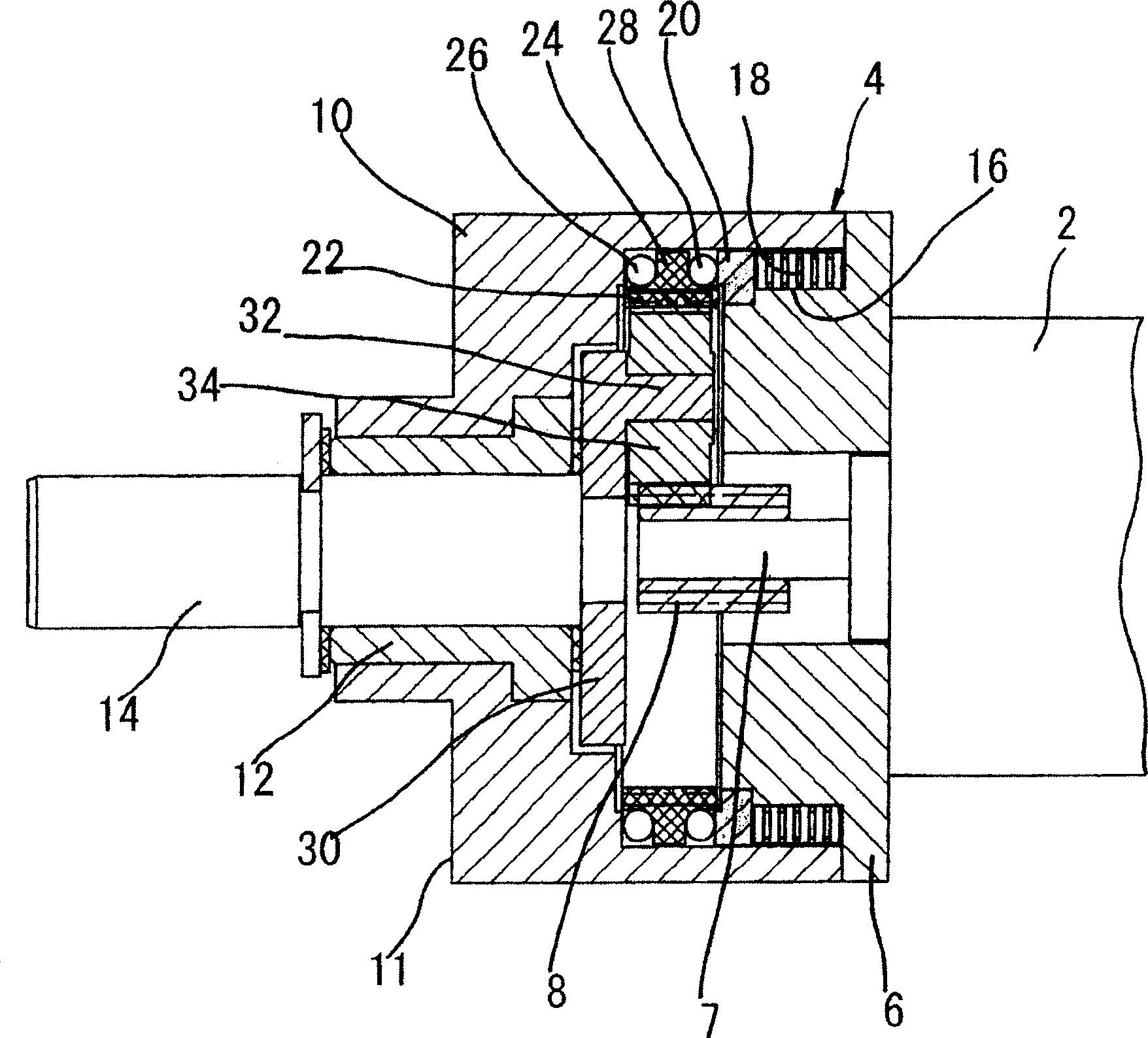
[0057] figure 1 It shows an embodiment in which the torque limiter is provided in the primary speed reducer, and in the figure, the reference numeral 2 is a speed-reduced device, which is constituted by a DC motor. A cover 6 of the planetary gear reducer 4 with a torque limiter is fixed to the casing of the above-mentioned reduction gear 2 . The output shaft of the above-mentioned reduction gear device 2 constitutes the input shaft 7 of the present reduction gear 4 , and the sun gear 8 is fixed to the input shaft 7 .

[0058] Reference numeral 10 denotes a cylindrical casing of the present reducer 4, a bearing 12 is fixed to the inner diameter portion of the casing, and an output shaft 14 is positioned on an extension line coaxial with the input shaft 8 and is rotatably supported by the bearing 12. superior. A disk-shaped cover 6 having a shaft...


PUM


Abstract

The invention provides a planetary gear type reduction gear with torque limiter that demonstrates always stably torque limiter function, and the invention is characterized in that an input shaft and an output shaft 7 consisting of an output shaft of a DC motor and an output shaft 14 are journalized on a stationary member 11, and at least one stage of the planetary gear type reduction mechanism comprising a central gear 8, a planetary gear 34 meshed with the central gear 8, an inner gear 22 meshed with the planetary gear 34, and a carrier 30 journalizing the planetary gear 34 and a torque limiter are provided between the input shaft and the output shaft.

Description

technical field [0001] The present invention relates to a planetary gear reducer with a torque limiter, and more particularly, to a planetary gear reducer having a torque limiter utilizing the frictional resistance of a friction member in the axial direction of the ring gear. Background technique [0002] A planetary gear reducer is assembled to a shaft of a DC motor, and a reduction mechanism that outputs based on a large reduction ratio has been known. [0003] Since the DC motor is a structure in which the shaft is rotated by applying current to the coil, it has poor performance against a large load from one side of the shaft. That is, if any load is applied to the shaft, if the rotation of the motor shaft continues to be stopped, the current applied to the above-mentioned coil will increase, and the motor will reach a high temperature, causing problems such as burning or melting of insulating materials, short circuits, and poor contact. [0004] In addition, when a redu...

Claims


Application Information

Patent Timeline
IPC IPC(8): F16H1/28
CPCF16H1/46
Inventor 加藤信一榎本勇生宇塚和夫
Owner TOK BEARING CO LTD
Why Eureka
Try Eureka