
Adjuster

A technology of regulators and detectors, applied in the field of regulators, can solve problems such as high output voltage, increasing the driving ability of PMOS transistor B, and damage to output load devices

Active Publication Date: 2006-12-20
EMTOPS ELECTRONICS CORP
View PDF3 Cites 0 Cited by
  • Summary
  • Abstract
  • Description
  • Claims
  • Application Information

AI Technical Summary

Problems solved by technology

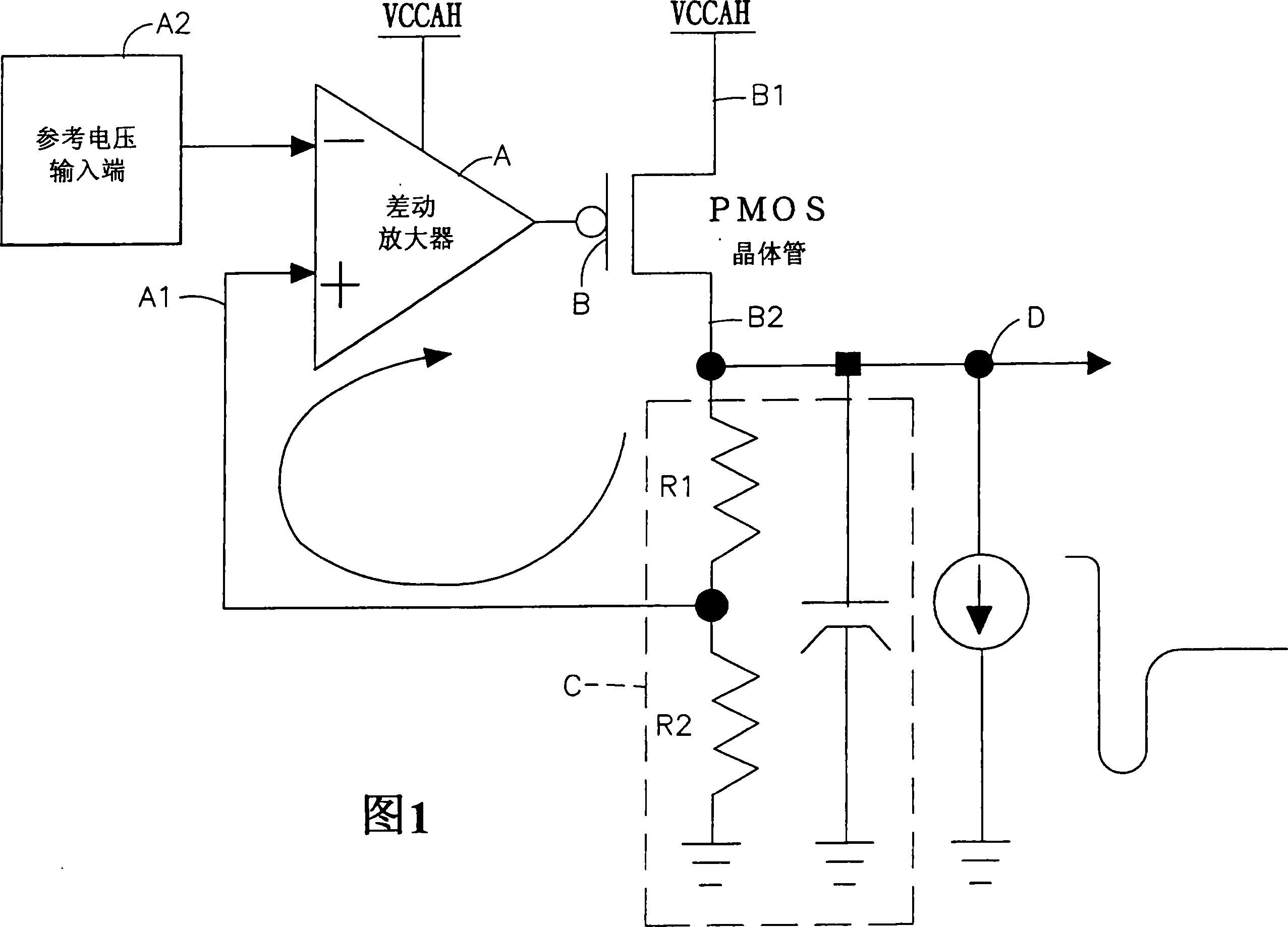
[0003] When the system starts to operate, its output voltage (VOUT) starts from the ground potential. At this time, the gate potential of the PMOS transistor B will be pulled to the ground potential rapidly due to the influence of the feedback circuit, so as to increase the driving ability of the PMOS transistor B, so , the feedback device C will instantly rise to the power supply voltage (VCCAH), causing the output voltage to be too high. This phenomenon often easily causes abnormal damage to the output load device (such as FLASH)

Method used


Image

  • Adjuster
  • Adjuster
  • Adjuster

Examples


Embodiment Construction

[0031] In order to achieve the above purpose and effect, the technical means and structure adopted by the present invention will be described in detail with reference to the accompanying drawings for the preferred embodiments of the present invention. Its features and functions are as follows for complete understanding.

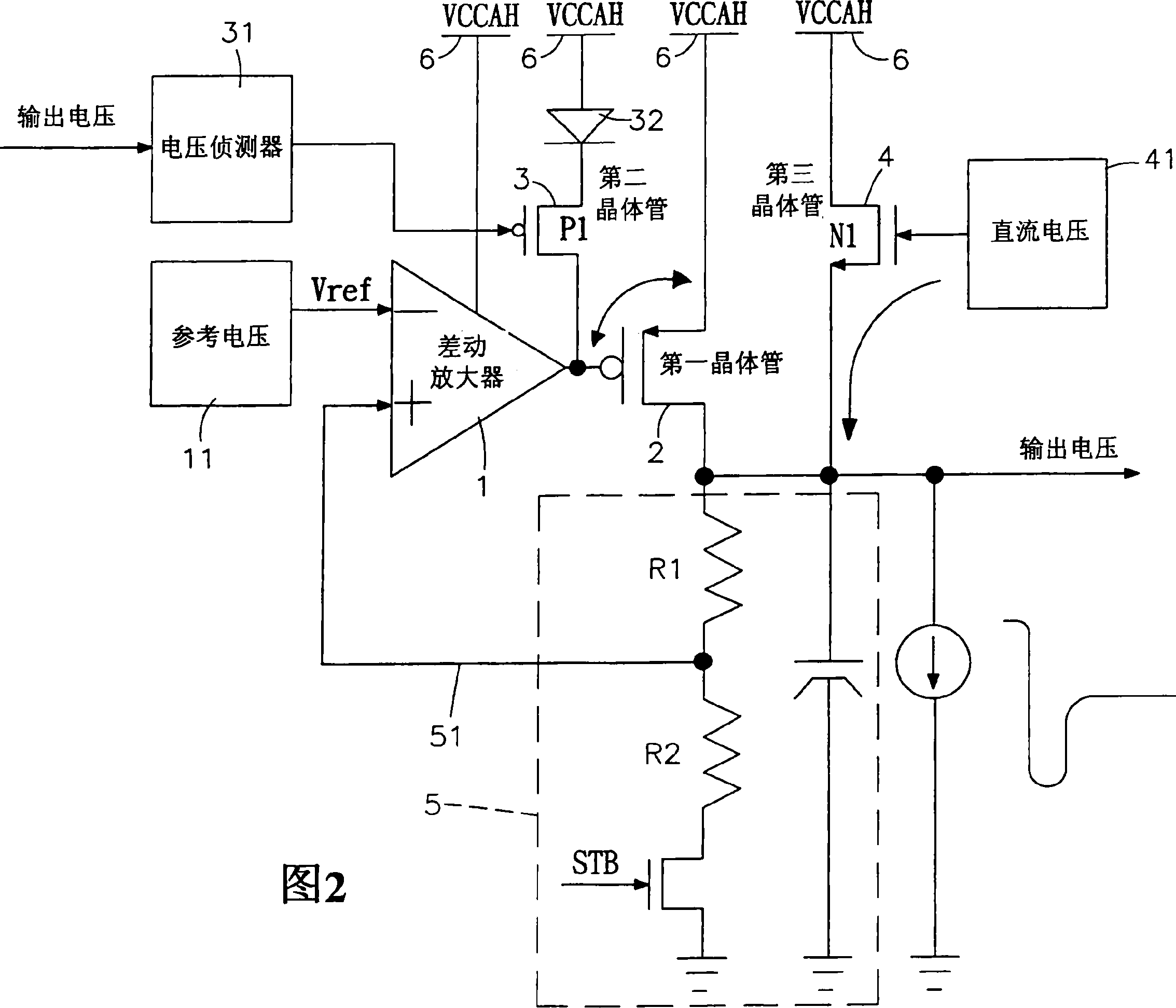
[0032] Please refer to Fig. 2, which is a schematic circuit diagram of the adjuster of the present invention. It can be clearly seen from the figure that the adjuster of the present invention is provided with a differential amplifier 1, a first transistor 2, a second transistor 3, and a third transistor 4 , feedback device 5 and power supply 6; wherein:

[0033] The differential amplifier 1 is connected to the power supply 6, and the differential amplifier 1 is input with a reference voltage 11 and a feedback voltage 51 output by the feedback device 5, and when the feedback voltage 51 is lower than the reference voltage 11, the differential amplifier 1 It wil...


PUM


Abstract

The invention relates to an adjuster, which comprises a differential amplifier connected to the reference voltage and the first transistor, wherein the first transistor is connected to a feedback device; the second transistor is connected between the first transistor and the differential amplifier; the second transistor is connected to a voltage detector and a diode that connected to the power supply; the voltage detector will continuously detect the output voltage between the feedback device and the first transistor; when said voltage is lower than the voltage of power supply, the voltage detector will send one signal to power the second transistor, and limit the grid-source voltage (VGS) of first transistor at the voltage difference of one diode, to reduce the pushing ability of first transistor and reduce the sudden climb over phenomena of output voltage (VOUT).

Description

technical field [0001] The invention relates to a regulator, especially a regulator that uses a detection device to detect the voltage between a load device and a first transistor, so as to reduce the phenomenon that the output voltage is too high due to plugging or starting. Background technique [0002] With the rapid development of electronic technology, electronic products have been widely used by the public, such as: computers, mobile phones, flash drives, digital cameras, etc., and the functions of these products are also increasing day by day, and the power consumption required by the system is bound to increase. (Sleep) mode reduces power consumption, and when switching from standby mode to working state, when the system is turned on or the feedback device is started, attention must be paid to the sudden rise of the output voltage (VOUT) to avoid damage to other devices due to excessive output voltage. load circuit, and in the standby current consumption, for battery...

Claims


Application Information

Patent Timeline
IPC IPC(8): H03K17/22H03K17/08
Inventor 颜暐駩许智仁
Owner EMTOPS ELECTRONICS CORP
Learn More