Oil field drill top-drive motor ventilator

A technology for ventilators and drilling rigs, applied in electromechanical devices, machines/engines, cooling/ventilation devices, etc., can solve the problem of not being equipped with ventilators, and achieve the effects of good aerodynamic performance, compact structure and low noise

Inactive Publication Date: 2006-12-27
CRRC YONGJI ELECTRIC CO LTD
View PDF0 Cites 4 Cited by
  • Summary
  • Abstract
  • Description
  • Claims
  • Application Information

AI Technical Summary

Problems solved by technology

Therefore, the top drive motors of various oil field dri

Method used


Image

  • Oil field drill top-drive motor ventilator

Examples


Embodiment Construction

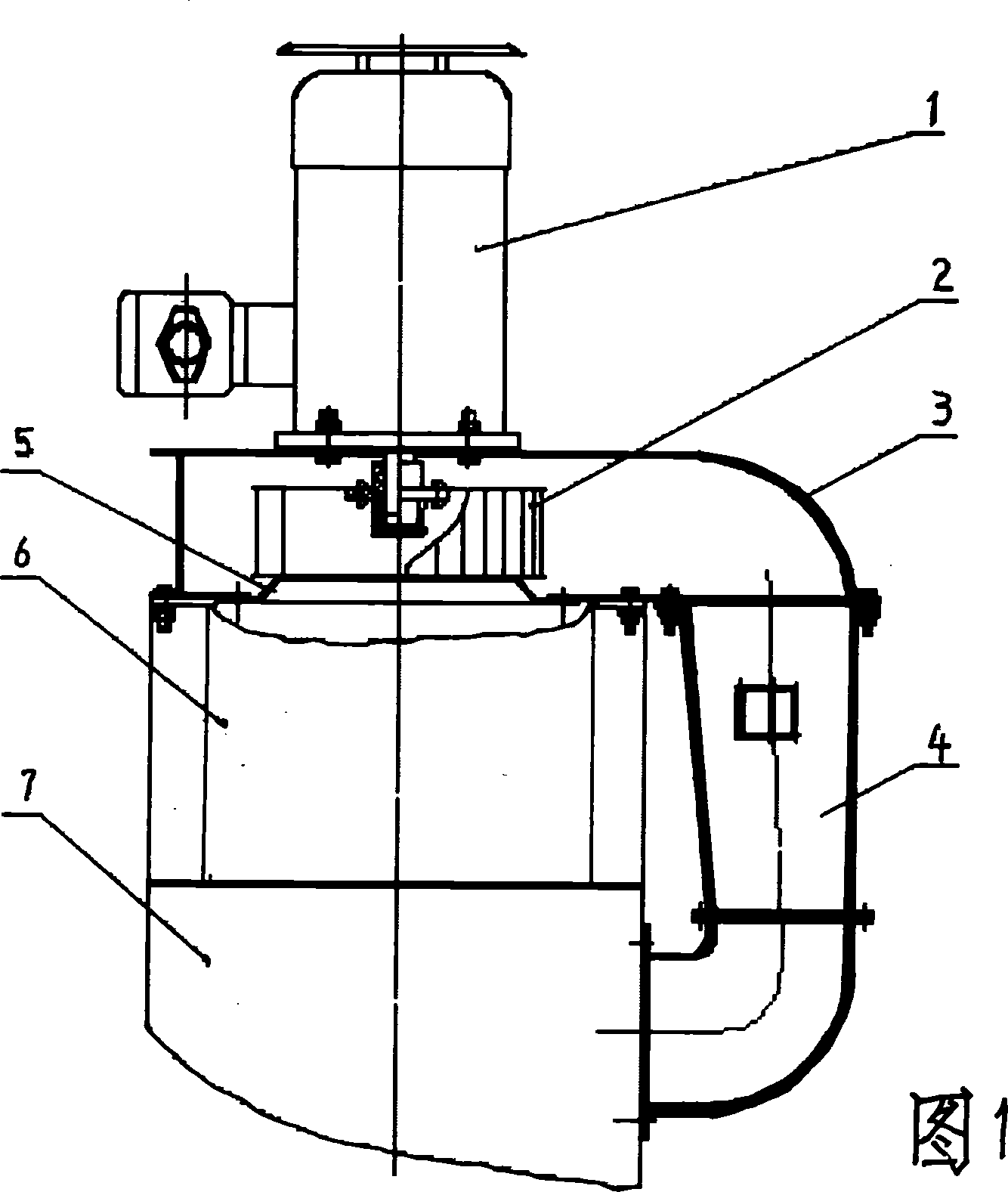
[0008] The top drive motor ventilator of the oil field drilling rig includes a volute 3, a fan motor 1 is fixed on one side of the volute, an impeller 2 driven by the fan motor is inside the volute, and an air duct 4 is fixed on the air outlet of the volute. A current collector 5 is fixed at the air inlet of the volute 3 . After the current collector 5 is molded with a hyperbola, it is assembled on the side plate 2 of the volute assembly with a flange, so that the air intake forms a high-pressure airflow, so that the fan can efficiently inhale cold air from the disc brake seat. During specific manufacturing, the blower motor 1 adopts the M2JA series 5.5kW explosion-proof motor of ABB Company, and its installation method is B5 installation method. The volute 3 is welded by steel plates, and the profile of its side plate 1 is the same as that of the common volute plate, and the fan drive motor is assembled on the side plate 1; It basically coincides with the disc brake seat. T...


PUM


Abstract

The related ventilator for drive motor of oil-field driller comprises: a scroll case with a ventilator motor on side and a driven impeller inside, and an air-duct fixed on case outlet. This invention can cool the disk braking device at one time, and has compact structure and well practice effect with low noise.

Description

technical field [0001] The invention relates to a ventilator for motor cooling, in particular to a top drive motor ventilator for an oil field drilling rig. Background technique [0002] Due to the particularity of the operating environment of the top drive motor of the oil field drilling rig, it does not have a supporting cooling fan. Therefore, the top drive motors of various oil field drilling rigs produced in China are not equipped with ventilators at present. Contents of the invention [0003] In order to solve the problem that the top drive motor of an oil field drilling rig has no matching fan, the present invention provides a top drive motor fan for an oil field drilling rig. [0004] The present invention adopts the following technical scheme: the top drive motor ventilator of the oil field drilling rig includes a volute, a fan motor is fixed on one side of the volute, an impeller driven by the fan motor is arranged inside the volute, and an output fan is fixed o...

Claims


Application Information

Patent Timeline
IPC IPC(8): H02K9/00F04D25/06F04D25/08
Inventor 罗汉牟景峰
Owner CRRC YONGJI ELECTRIC CO LTD
Why Eureka
Try Eureka