
Thread control device for a textile machine in particular for a shedding device

A technology of yarn control and opening device, applied in the cam opening mechanism, other opening mechanisms, knitting and other directions, can solve the problems of reduced loom efficiency, high cost, reduced motor speed, etc., and achieve the effect of simple structure and simple manufacturing

Active Publication Date: 2006-12-27
TEXTILMA AG
View PDF1 Cites 9 Cited by
  • Summary
  • Abstract
  • Description
  • Claims
  • Application Information

AI Technical Summary

Problems solved by technology

[0007] The disadvantage of the above technical solutions is the high cost of electric / pneumatic actuation of the valves
Thus, the entire controller of the pneumatic drive of the yarn control device has a large number of elements, such as non-return valves, pressure relief valves, pressure relief valves and electronic control units, which makes the system more prone to failure
In addition, the efficiency of the loom decreases due to a corresponding reduction in the motor speed in order to drain the lubricating oil, which occurs every 15 minutes
Furthermore, a reduction in the motor speed can have a negative effect on the textile quality, e.g. it can lead to slight variations in the width of the produced fabric

Method used


Image

  • Thread control device for a textile machine in particular for a shedding device
  • Thread control device for a textile machine in particular for a shedding device
  • Thread control device for a textile machine in particular for a shedding device

Examples


Embodiment Construction

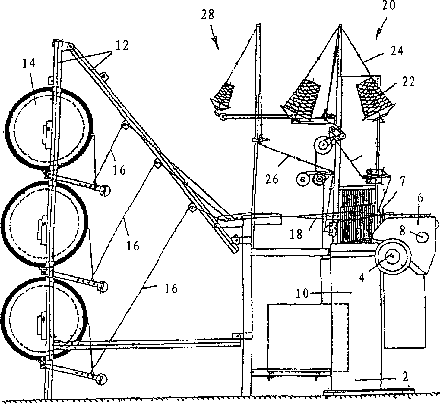
[0029] figure 1 Shown is a needle-type weaving machine with a frame 2 in which is mounted a main drive shaft 4 driving at least one weft needle 6 (not shown in more detail); a reed 7; fabric A take-up device 8 and a yarn control device formed as a heald frame device 10 . The needle loom has a beam support 12 carrying a warp beam 14 from which warp threads 16 are supplied to a heald frame arrangement 10 which opens the warp threads to form a shed 18 . Via the yarn supply device 20 , weft yarn 24 is supplied from the bobbin 22 to the weft yarn needle 6 , which guides the weft yarn loops into the shed 18 . The continuous loop of weft yarn can be knotted by itself, or by means of a tuck yarn 26 (not shown in more detail here) supplied to the knitting needles via another yarn supply device 28, to knot and secure the inserted Weft loops.

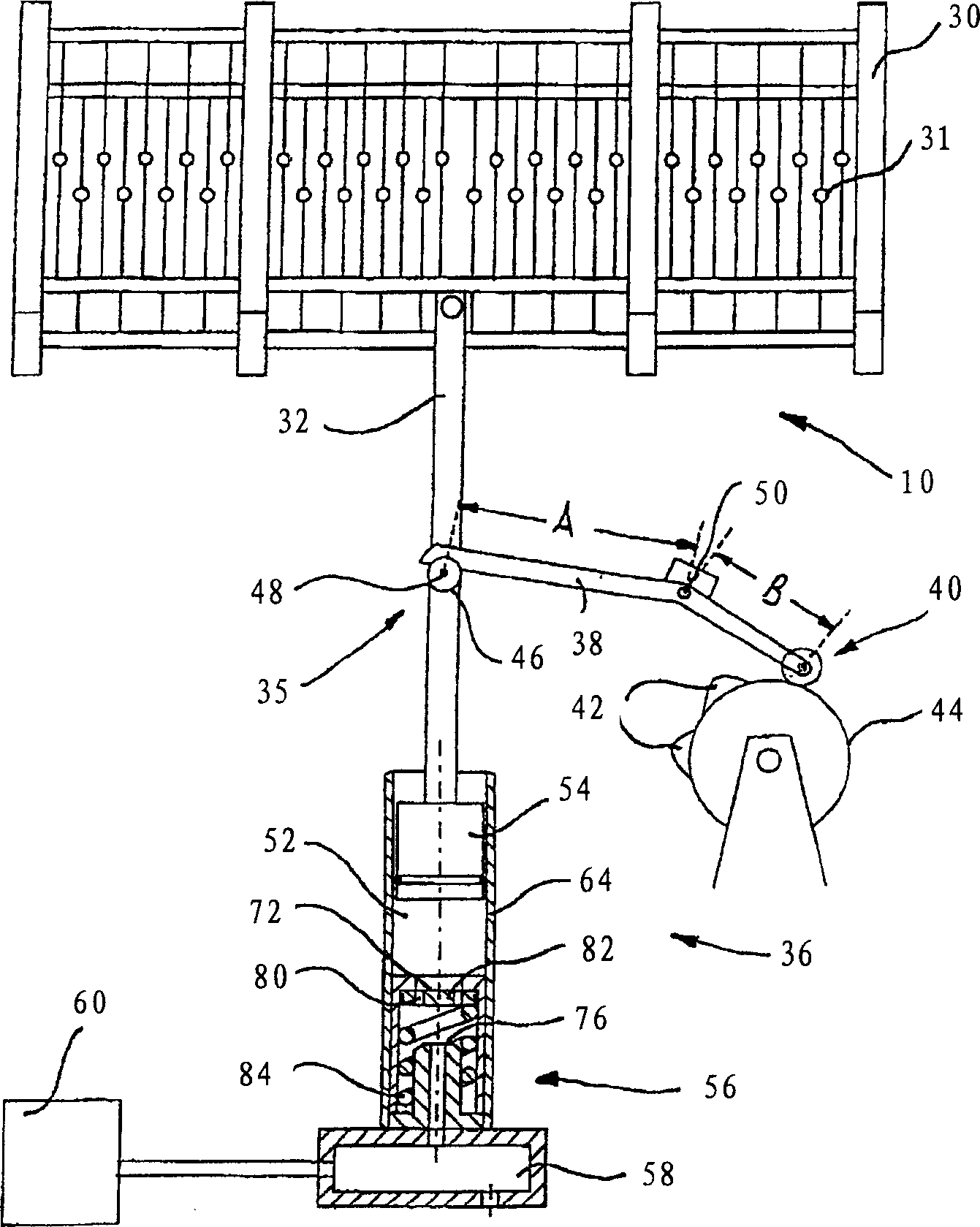
[0030] figure 2Shows a heald frame arrangement 10 in which, in each case, a plurality of heald frames 30 with thread guide elements 31 are c...


PUM


Abstract

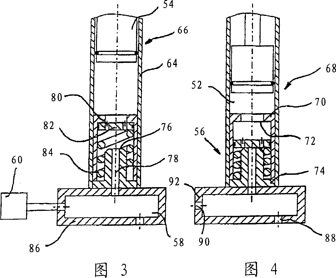
The invention relates to a thread control device for a textile machine, in particular, for a shedding device, with at least one thread guide body (31) which may be displaced in one displacement direction by means of a positive drive (35) and in the opposite direction by means of a non-positive, pneumatic return device (36). The return device (36) thus comprises a cylinder / piston unit (64,54), the cylinder chamber of which (52) is connected to a compressed gas source (60) by means of a valve (56). An improvement in control is achieved when the valve (56) comprises a first valve seat (72) connected to the cylinder chamber (52) and a second valve seat (76), between which a valve body (82), provided with at least one throttle point (80), may be displaced, pre-tensioned in the rest position by means of a spring (84) against the first valve seat (72), in which the throttle point (80) is ineffective and the valve body (82) blocks the communication with the compressed gas source (60) when the valve body (82) is in contact with the second valve seat (76).

Description

technical field [0001] The invention relates to a thread control device for a weaving machine, in particular for a shedding device, according to the preamble of claim 1 . Background technique [0002] A large number of yarn control devices for weaving machines are known. The closest prior art according to WO 97 / 08373 discloses a yarn control device designed with a drive and with return means for the yarn guiding member. In this case, the thread guide part is movable in one direction of movement by means of a positively designed drive and in the opposite direction of movement by means of a nonpositive and pneumatically designed return device, This return device acts in the opposite direction on the positive drive of the positive transmission. [0003] The pneumatic return device has a cylinder / piston assembly whose cylinder chamber is designed with an overpressure valve and has a non-return valve connected to a compressed air source. In this case, the air pressure in the c...

Claims


Application Information

Patent Timeline
Patent Type & Authority Applications(China)
IPC IPC(8): D03C5/00D03C13/00D04B27/26
CPCD03C13/025D03C5/00D03C13/00D03C5/04
Inventor 埃里克·比勒伯恩哈德·恩格瑟
Owner TEXTILMA AG
Learn More