Low resistance cyclonic liquid column type nozzle

A nozzle and anti-spin technology, which is applied in the field of low-resistance swirl liquid column nozzles, can solve the problems of lack of commercial desulfurization technology, incomplete design and manufacturing capabilities of flue gas desulfurization devices, and achieve high desulfurization efficiency and low operating costs. Reduction, construction cost reduction effect

Inactive Publication Date: 2007-01-03
南昌有色冶金设计研究院
View PDF0 Cites 6 Cited by
  • Summary
  • Abstract
  • Description
  • Claims
  • Application Information

AI Technical Summary

Problems solved by technology

[0002] China's large-scale coal-fired boiler flue gas desulfurization technology has experienced a tortuous development process from scratch. The country has almost brought together various international excellent desulfurization technologies, but my country still lacks commercia...

Method used


Image

  • Low resistance cyclonic liquid column type nozzle
  • Low resistance cyclonic liquid column type nozzle

Examples


Embodiment Construction

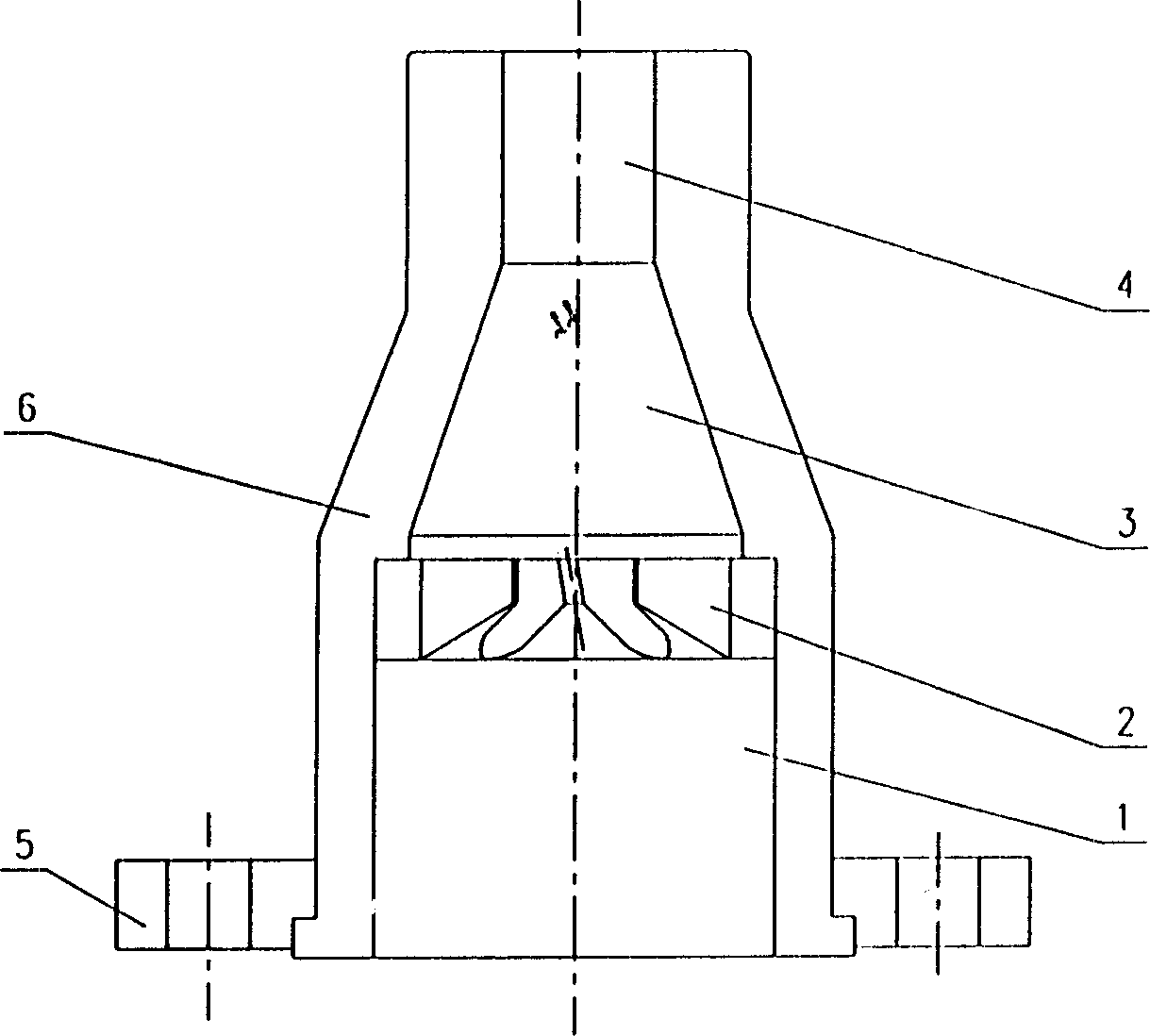
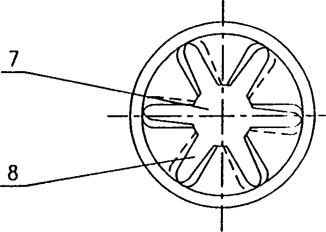
[0010] A nozzle applied to a high-efficiency pipe-type reaction desulfurization device for flue gas of a large-scale coal-fired unit in a thermal power plant. The steady flow section 1 is provided with a connecting flange 5 and a riser base 6 , and the riser 2 is provided with a central hole 7 and side flow holes 8 .

[0011] The liquid first passes through the steady flow section 1 to stabilize the flow, and distributes the throughput of the liquid through the center hole 7 and the side flow groove 8 of the riser core 2, so that part of the liquid obtains the initial rotational speed; the rotating liquid in the mixing cone 3 is further accelerated and The preliminary mixing of the rotating liquid and the direct injection liquid is completed, and the liquid is accelerated to the design flow rate through the acceleration tube 4, and the ejection nozzle is in contact with the gas.


PUM


Abstract

The present invention discloses one kind of nozzle for efficient tubular reaction desulfurizing device in large coal-burning unit of thermal power plant. The nozzle has the structure comprising a flow stabilizing section, a spraying core, a mixing conic pipe and a speeding pipe. The present invention has the advantages of adaptation to wet limestone-gypsum desulfurizing process, high jamming resistance, simple inner member and small nozzle body resistance loss.

Description

technical field [0001] The invention relates to a nozzle used for a flue gas desulfurization device of a large coal-fired unit in a thermal power plant, namely a low-resistance swirl liquid column nozzle. Background technique [0002] China's large-scale coal-fired boiler flue gas desulfurization technology has experienced a tortuous development process from scratch. The country has almost brought together various international excellent desulfurization technologies, but my country still lacks commercial desulfurization technologies suitable for my country's national conditions, especially in my country. It is not yet fully capable of designing and manufacturing flue gas desulfurization devices for coal-fired units in large thermal power plants. Contents of the invention [0003] The purpose of the present invention is to provide a nozzle suitable for the flue gas characteristics of a large coal-fired unit in a thermal power plant for a high-efficiency pipeline reaction des...

Claims


Application Information

Patent Timeline
IPC IPC(8): B05B1/00B01D53/48
Inventor 潘永涟王政才
Owner 南昌有色冶金设计研究院
Why Eureka
Try Eureka