Wire hook former
A forming device and wire hook technology, applied in the field of machinery, can solve the problems of frequent replacement of processing sites for semi-finished products, occupy a large area of the site, and many production equipment, and achieve the effects of fast production speed, good molding consistency, and high work efficiency
- Summary
- Abstract
- Description
- Claims
- Application Information
AI Technical Summary
Problems solved by technology
Method used
Image

Examples
Embodiment Construction
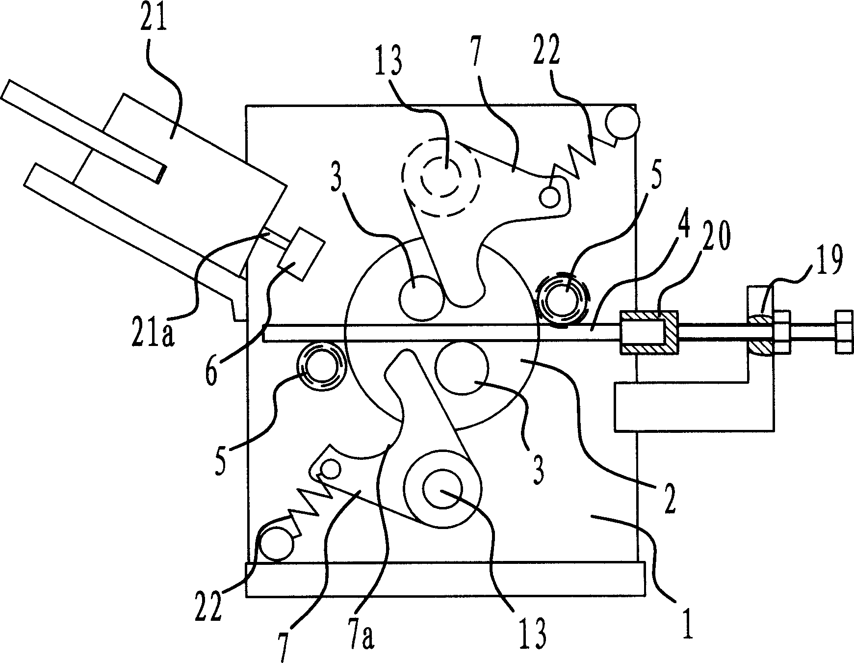
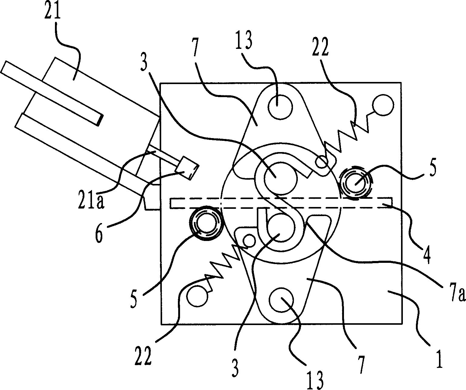
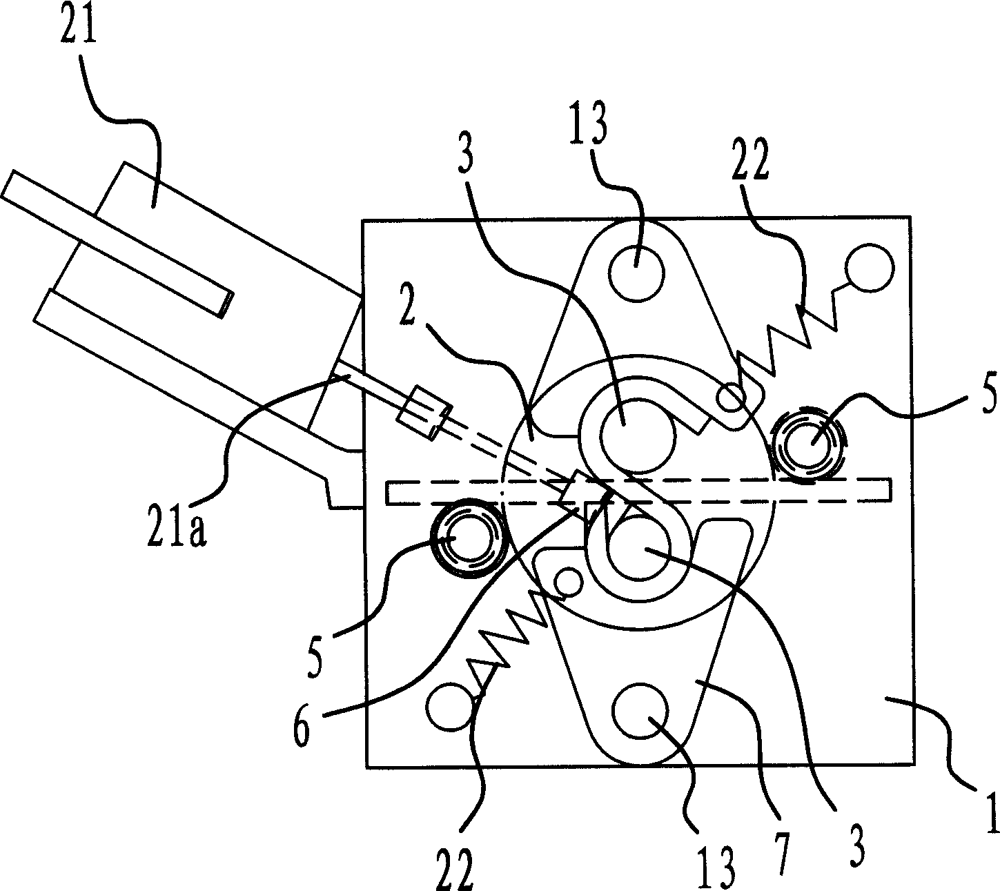
[0031] Such as Figure 1 to Figure 5 As shown, the wire hook forming device includes a forming seat 1 and a rotating disk 2 arranged thereon. The turntable 2 is provided with two staggered forming twist wheels 3 which can rotate with the turntable 2 , and there is a gap between the two forming twist wheels 3 for the wire 4 to pass through. On the forming seat 1, there are two forming retaining wheels 5 which are located at the periphery of the turntable 2 and can block the two ends of the wire 4, and a retractable pressing block 6 is arranged on one side of one of the forming retaining wheels 5. The top pressing block 6 is fixed on the end of the push rod 21a of the hydraulic cylinder 21 . Two rotatable forming plates 7 with arc-shaped notches 7a are symmetrically arranged on the periphery of the turntable 2 . The forming plate 7 is hinged on the forming seat 1 through a pivot 13 , and a tension spring 22 is arranged between the forming plate 7 and the forming seat 1 . One ...
PUM
 Abstract
Description
Claims
Application Information
 - Generate Ideas
- Intellectual Property
- Life Sciences
- Materials
- Tech Scout
- Unparalleled Data Quality
- Higher Quality Content
- 60% Fewer Hallucinations
Browse by: Latest US Patents, China's latest patents, Technical Efficacy Thesaurus, Application Domain, Technology Topic, Popular Technical Reports.
© 2025 PatSnap. All rights reserved.Legal|Privacy policy|Modern Slavery Act Transparency Statement|Sitemap|About US| Contact US: help@patsnap.com